
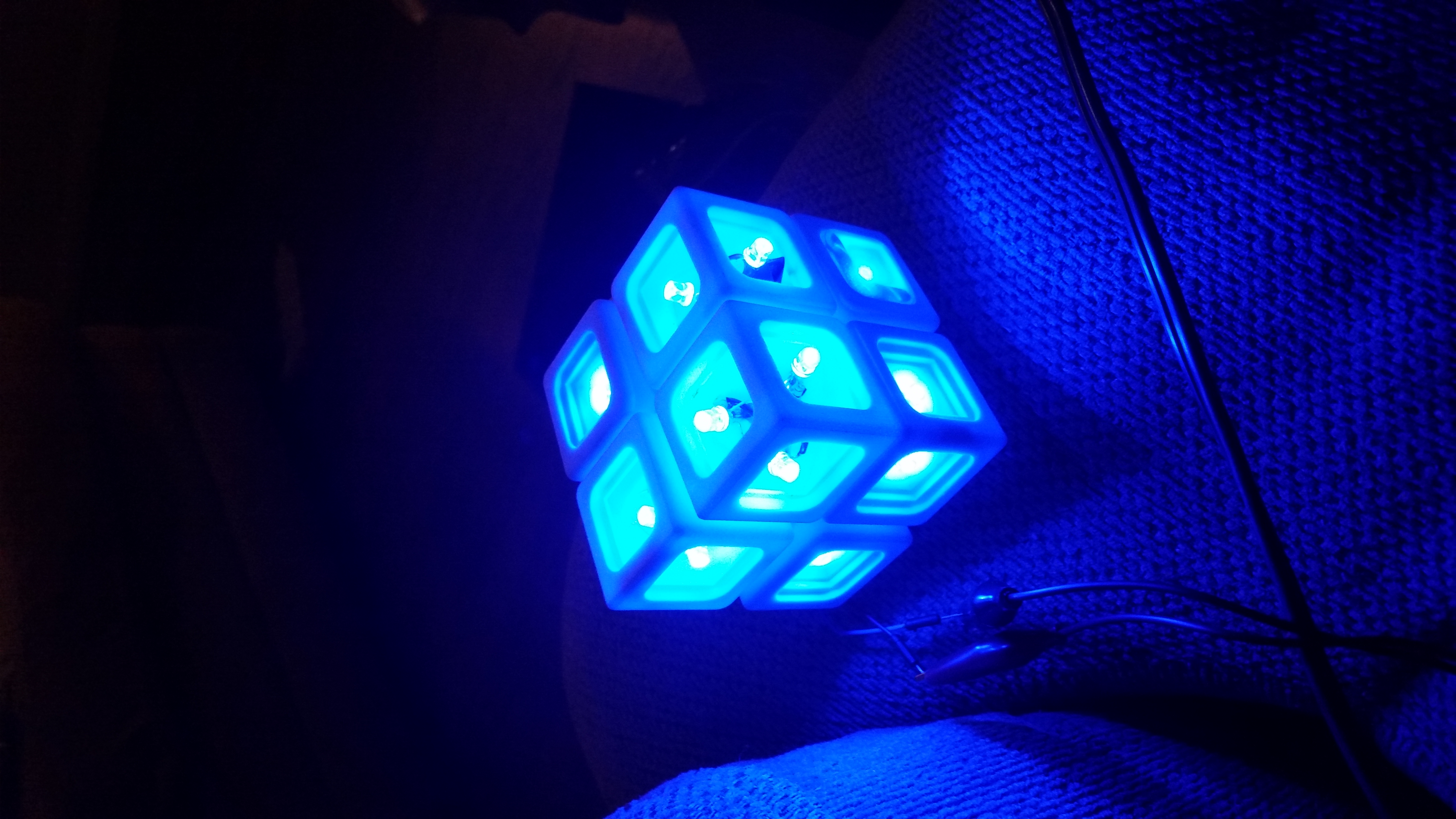
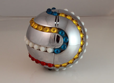
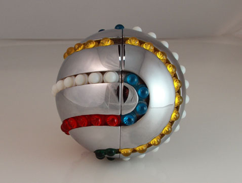
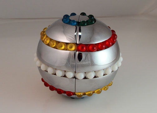
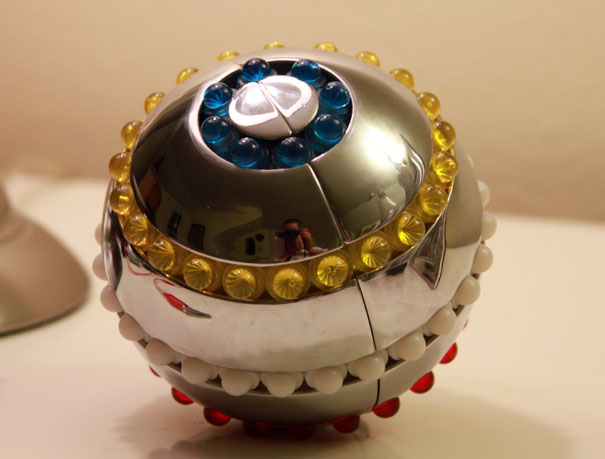
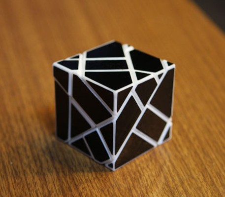
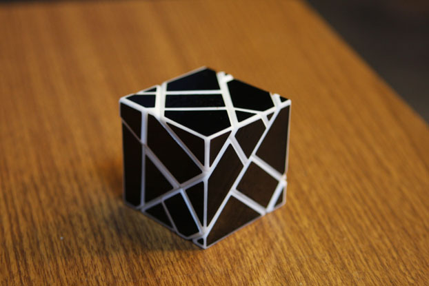
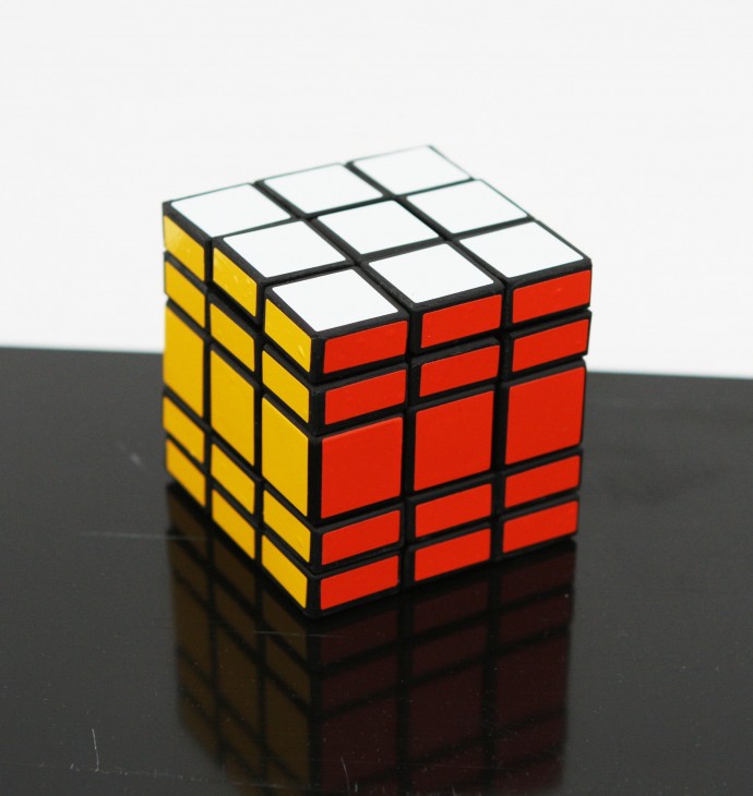
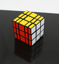
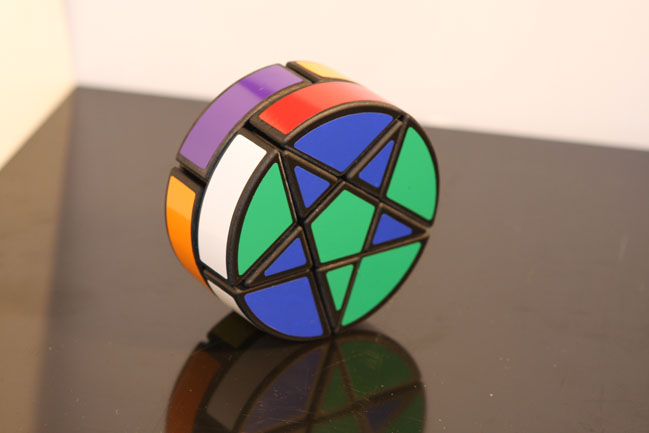
I’m happy to announce the Bit Box puzzle! This has been in the works for 9 years on and off. This is the 5th version, and it works!
It was inspired by the electronic game “Lights Out”, as well as “Merlin” and of course the original Rubik’s Cube.
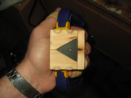
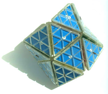
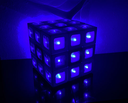
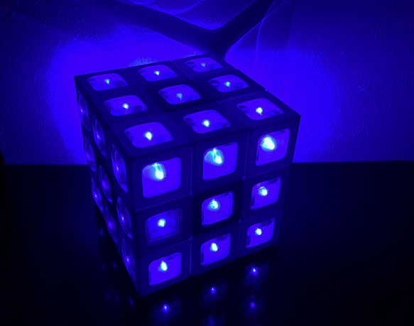
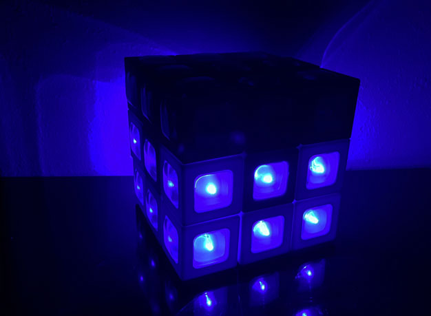
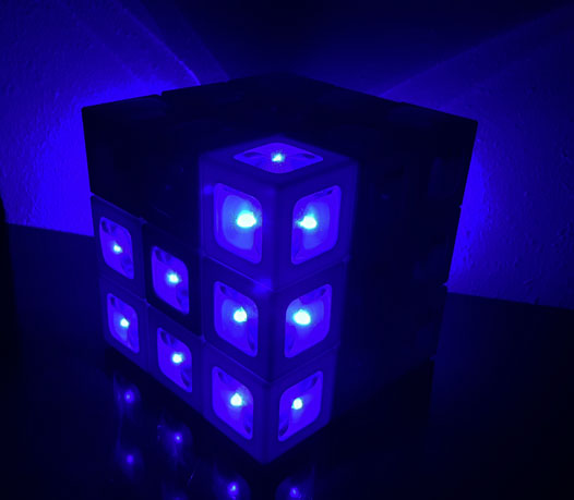
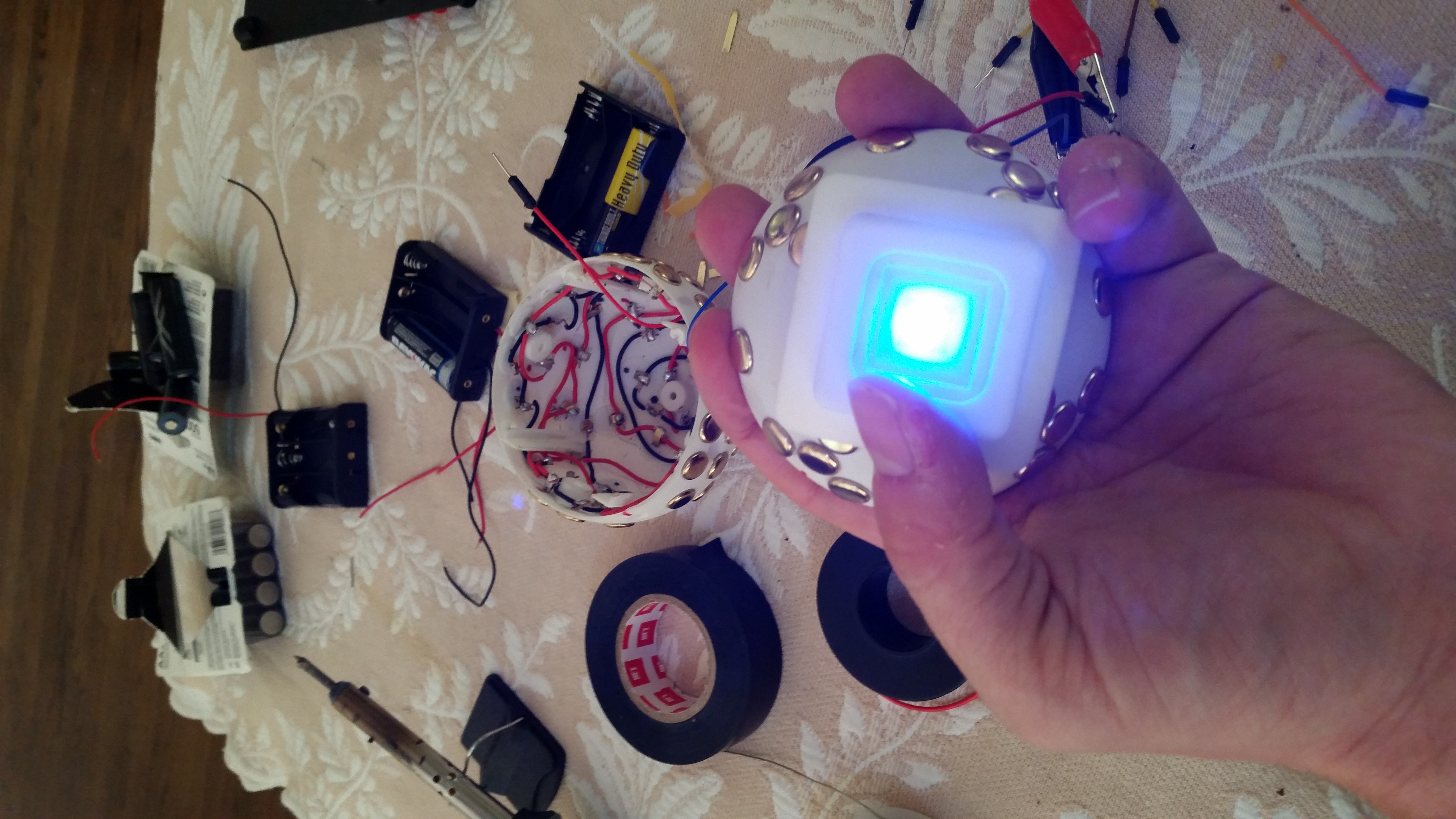
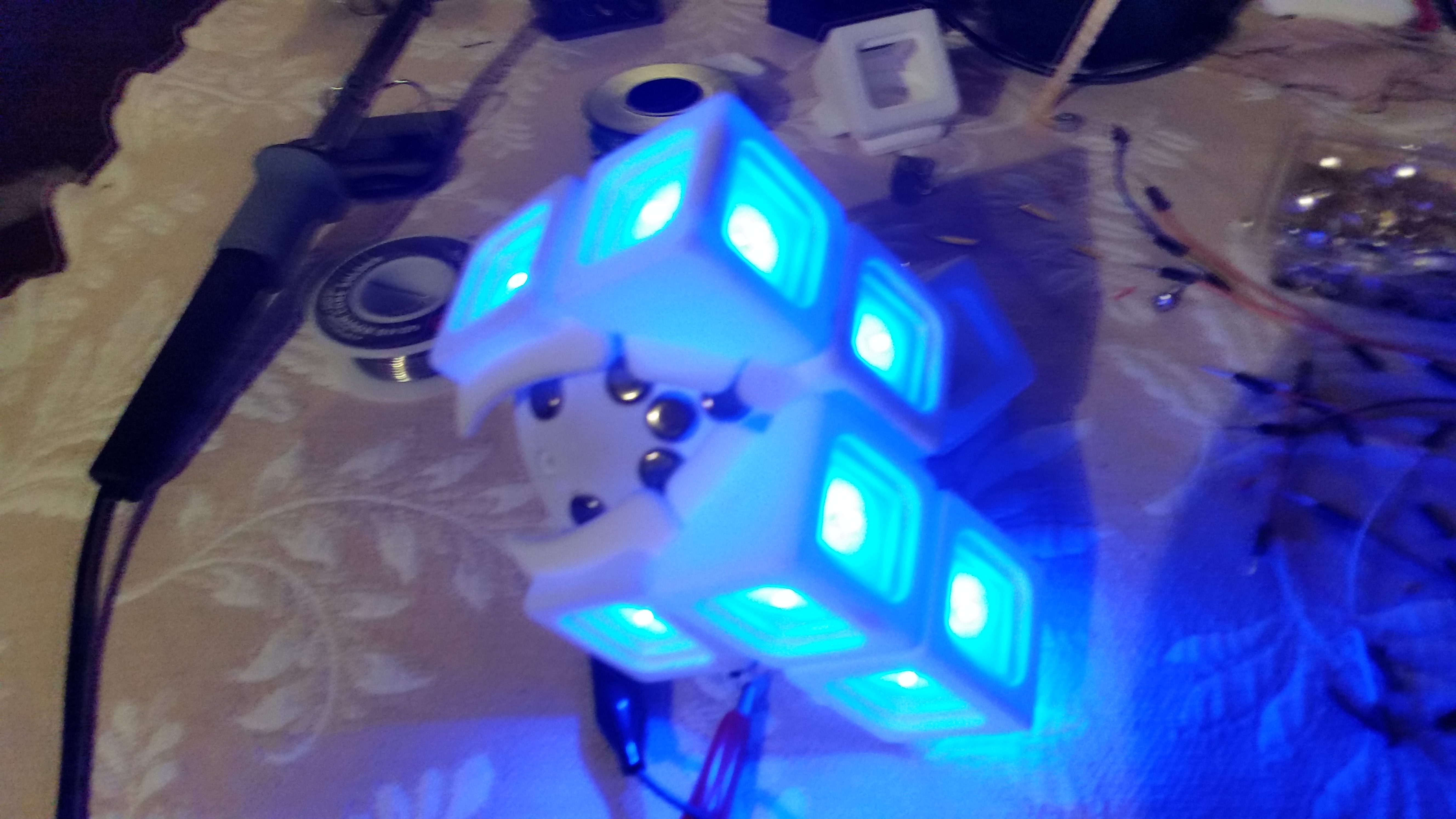
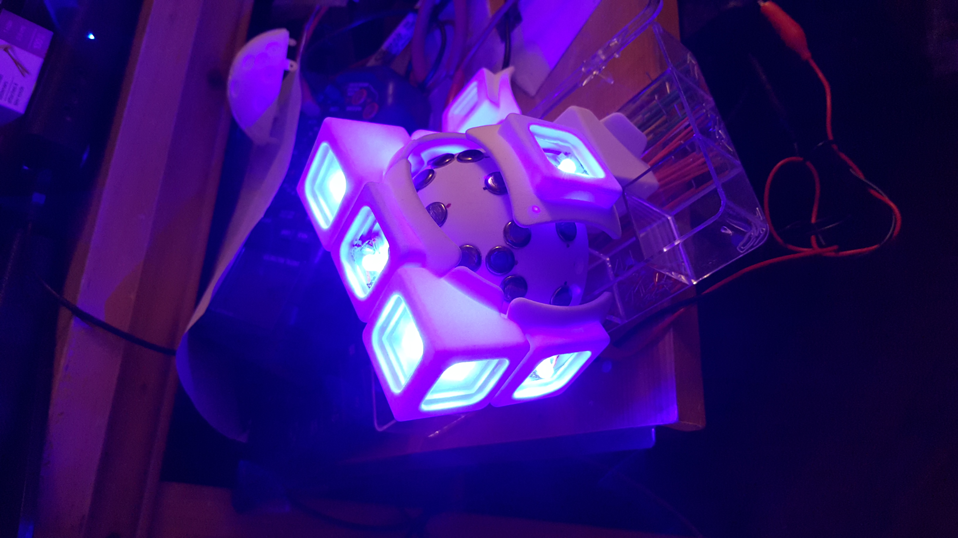
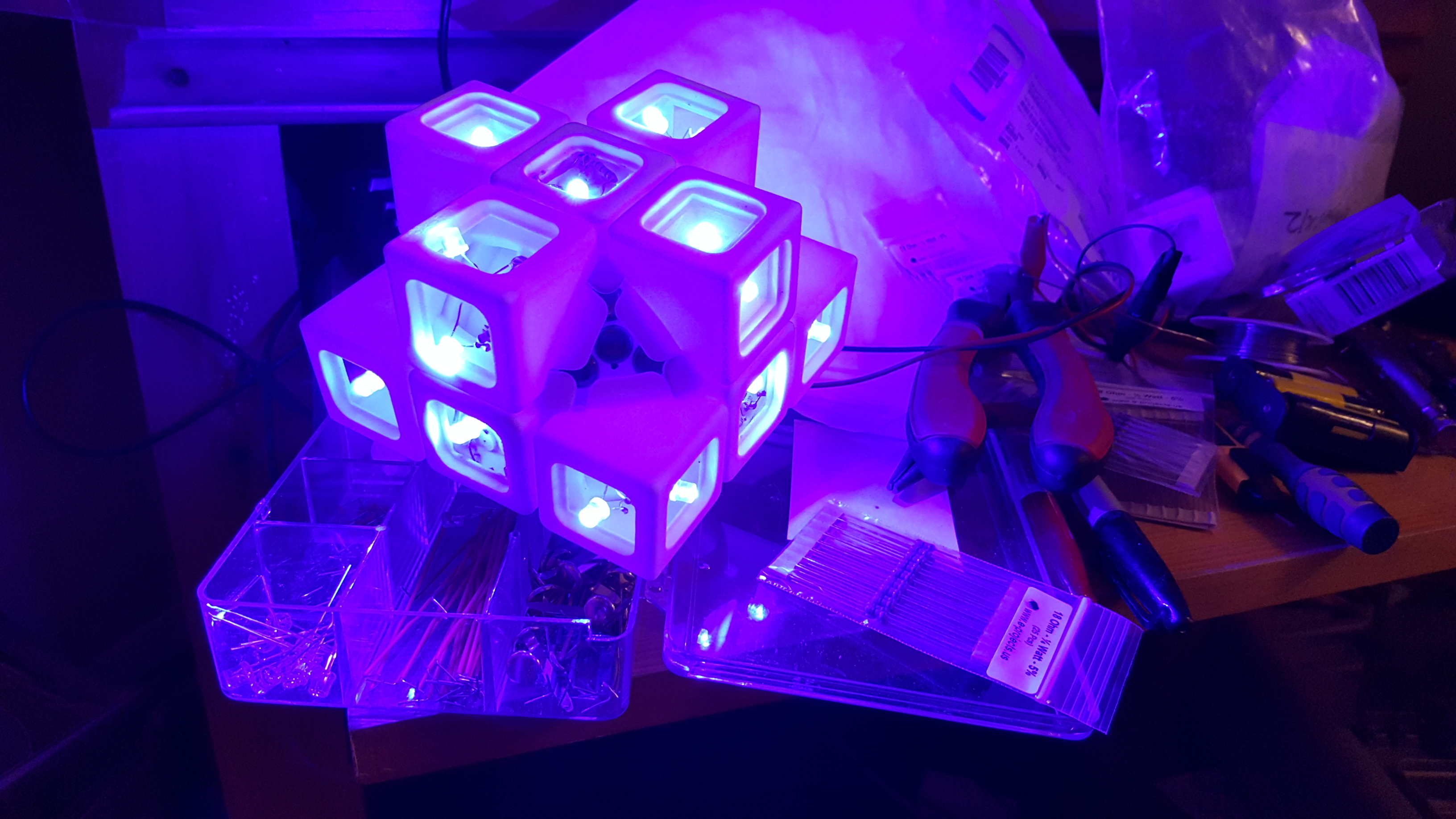
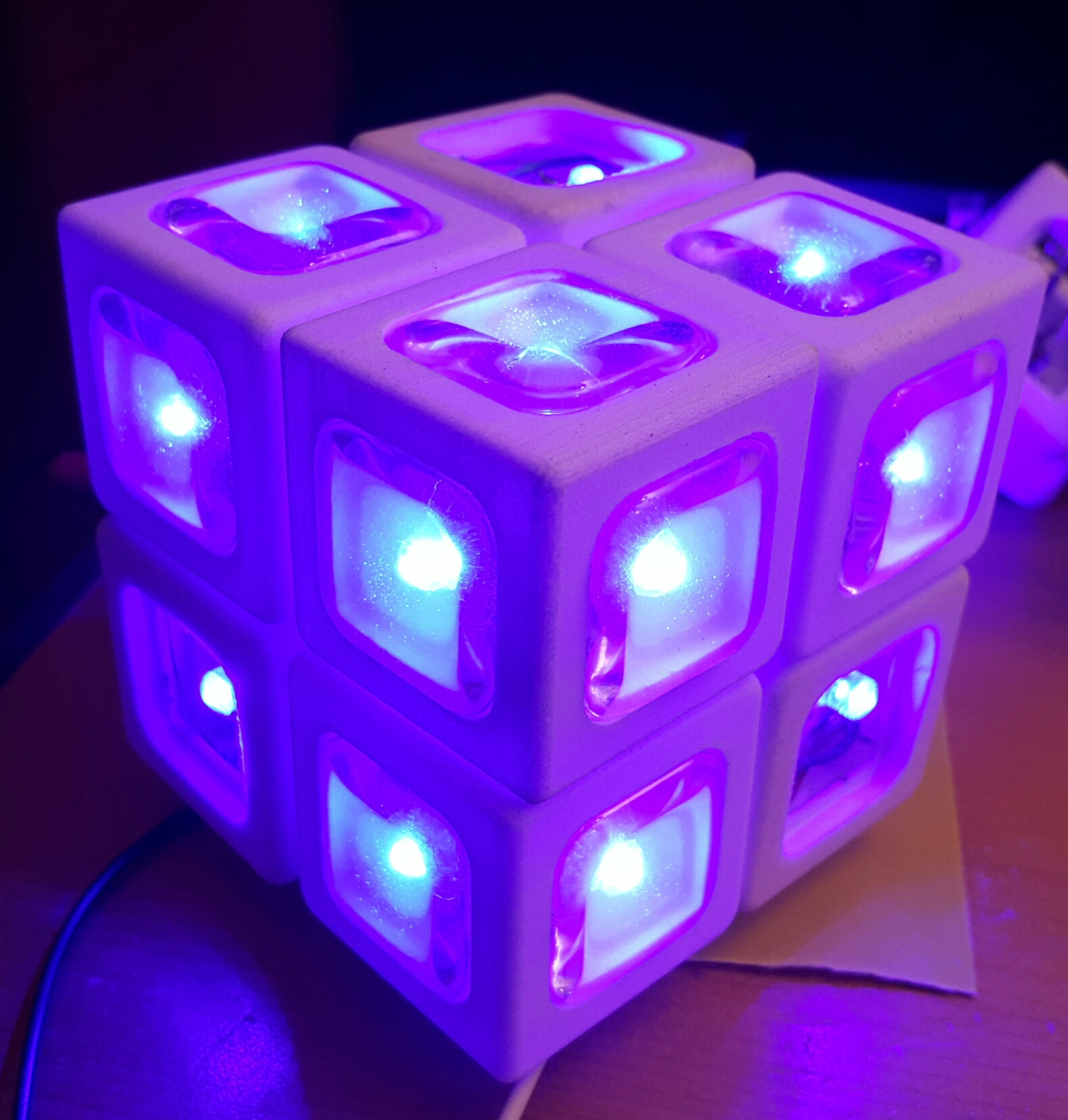
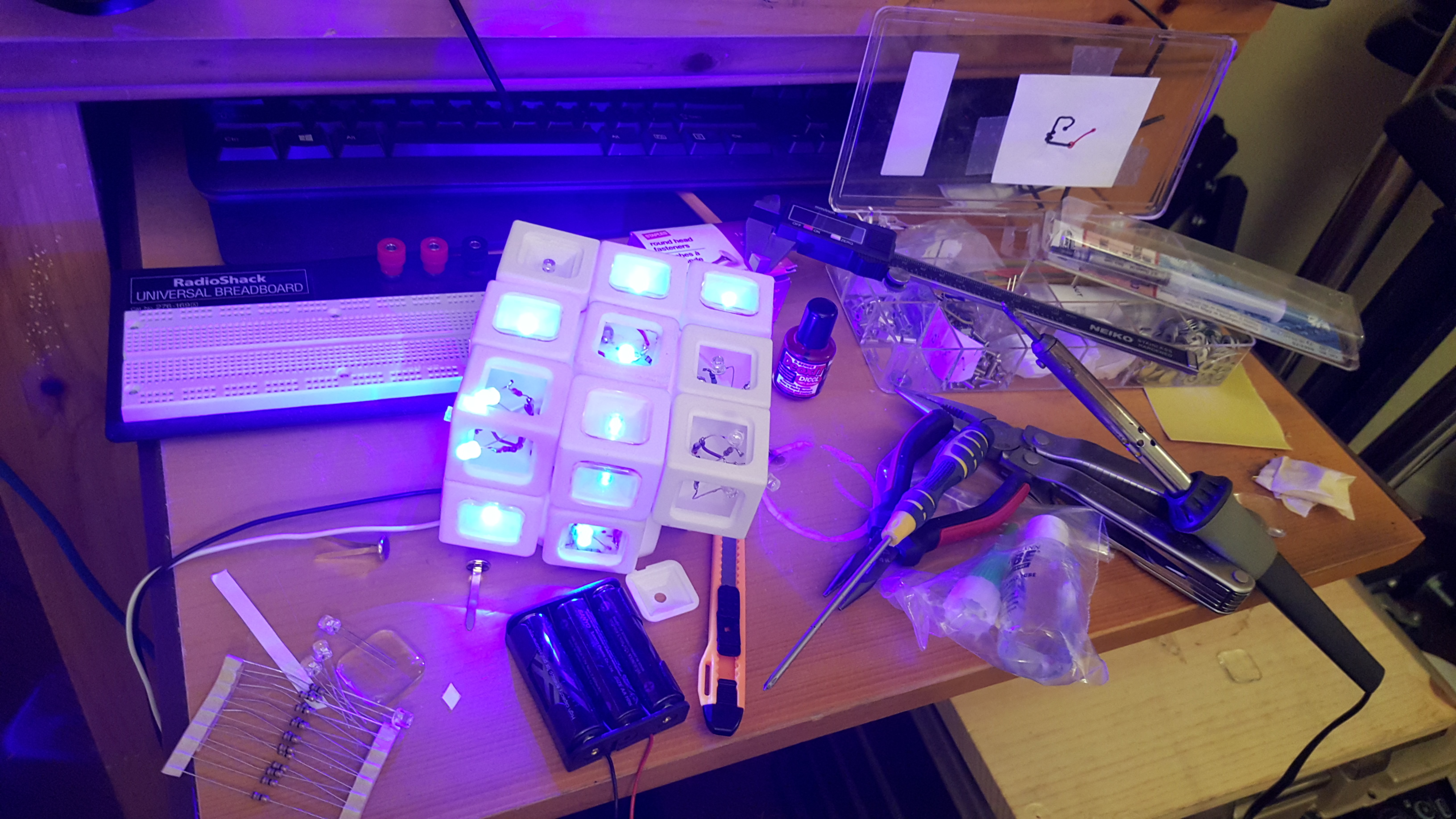
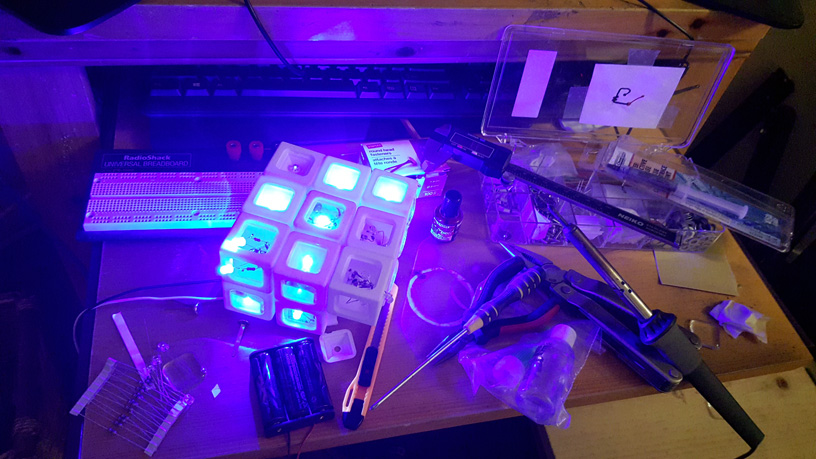
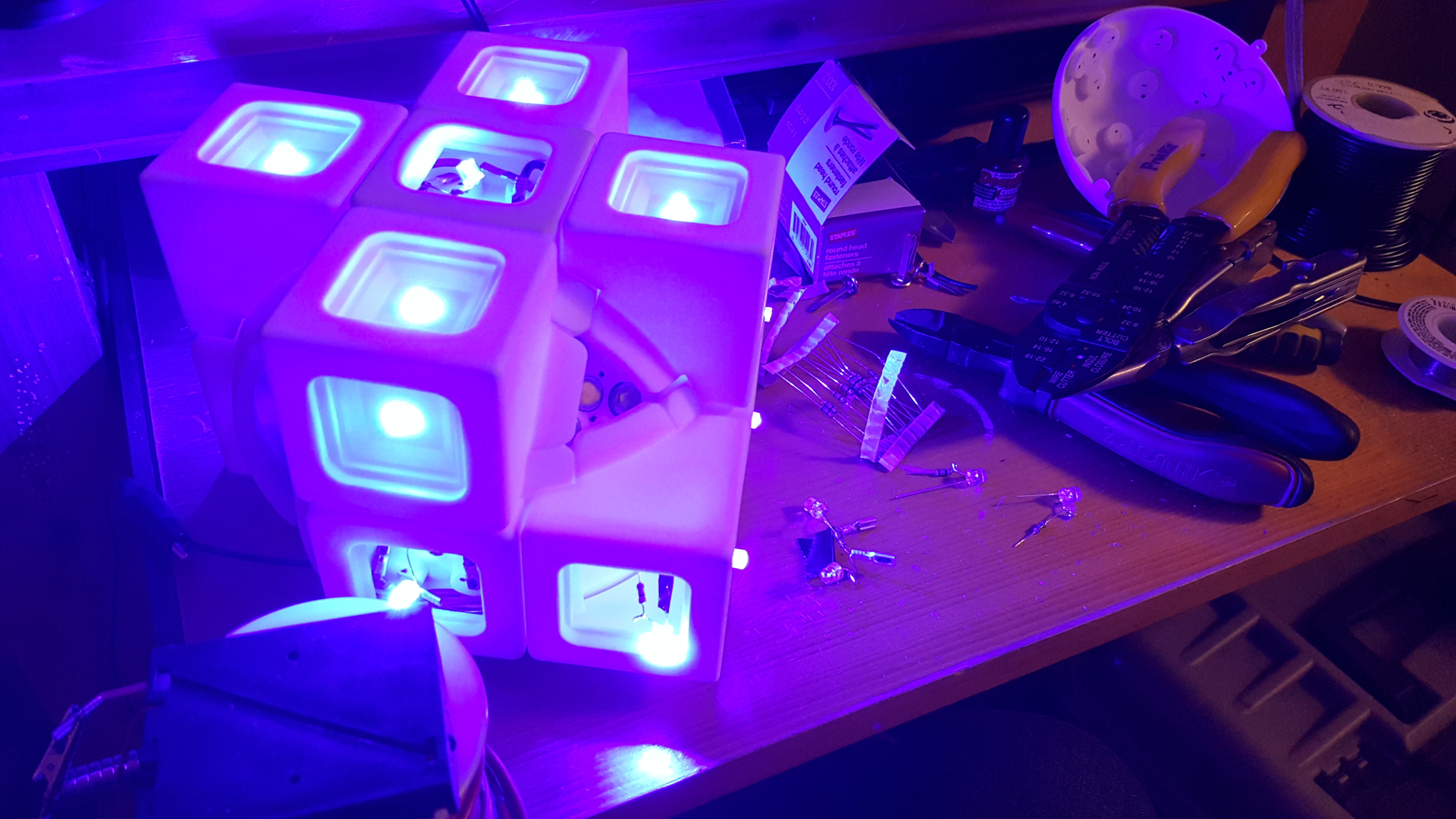
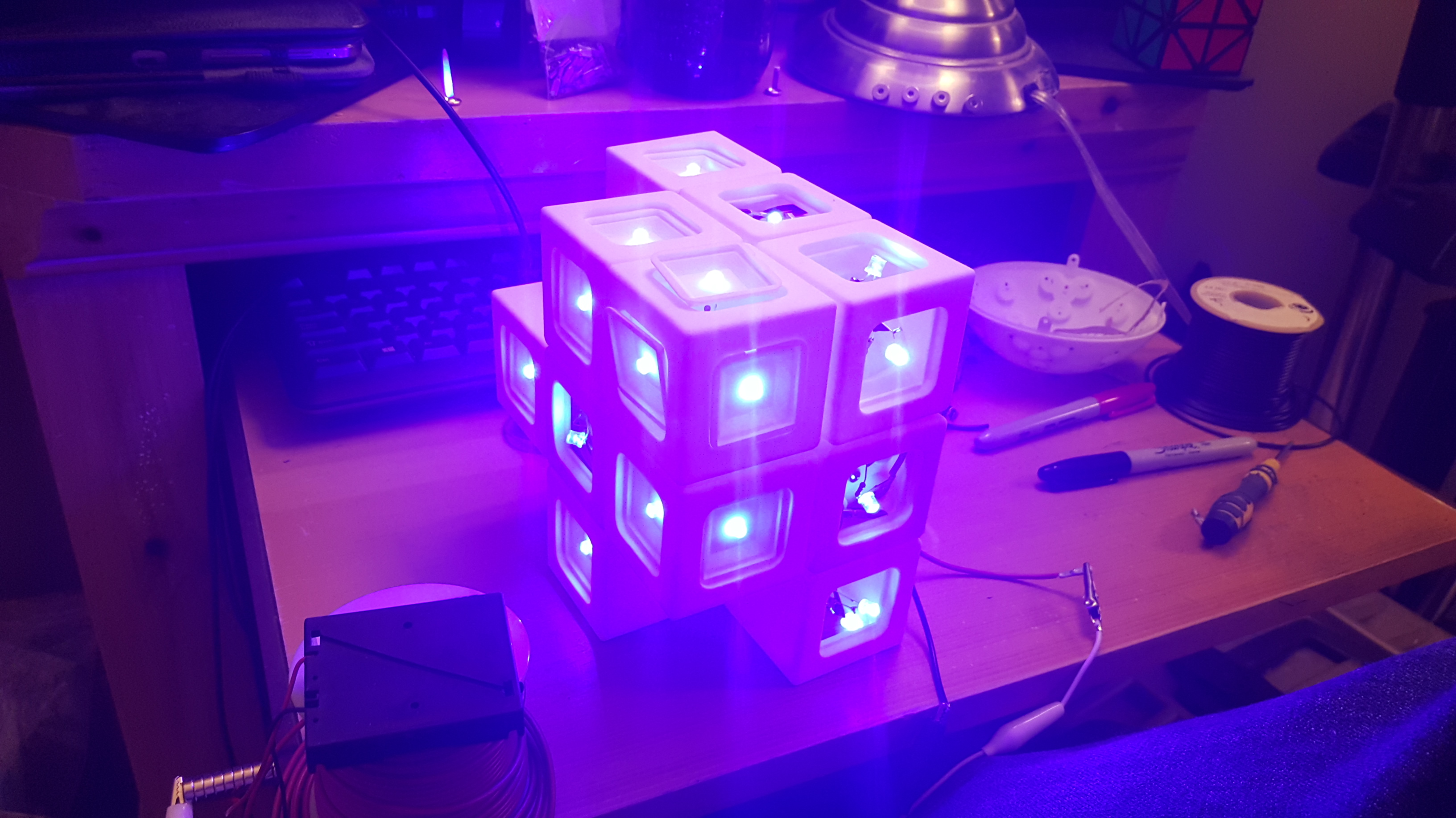
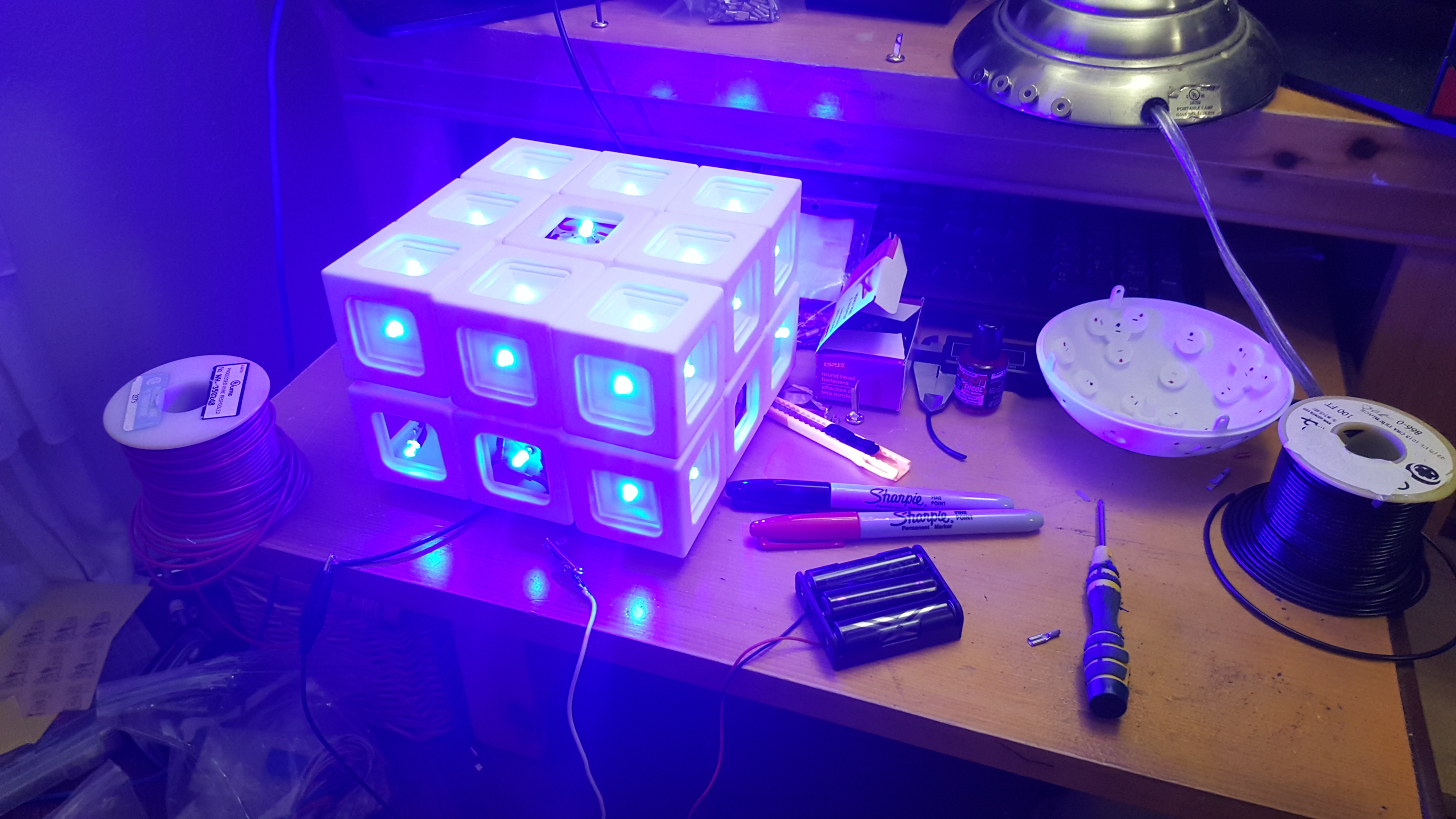
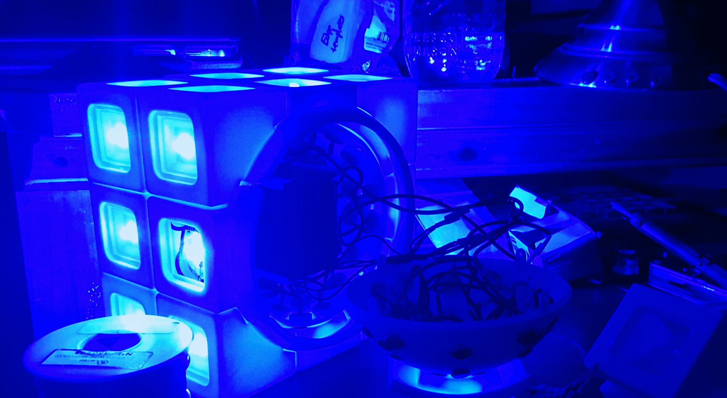
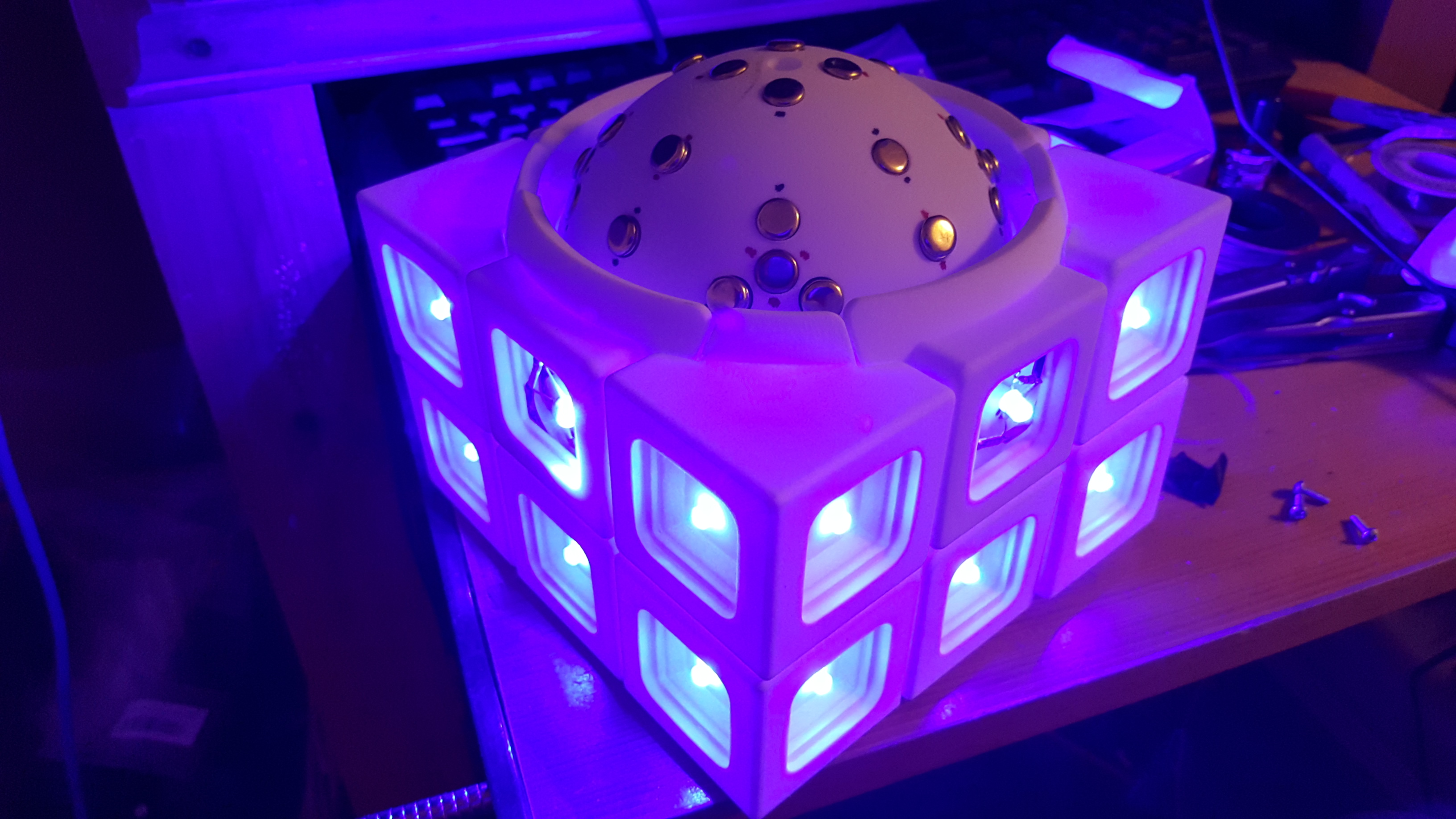
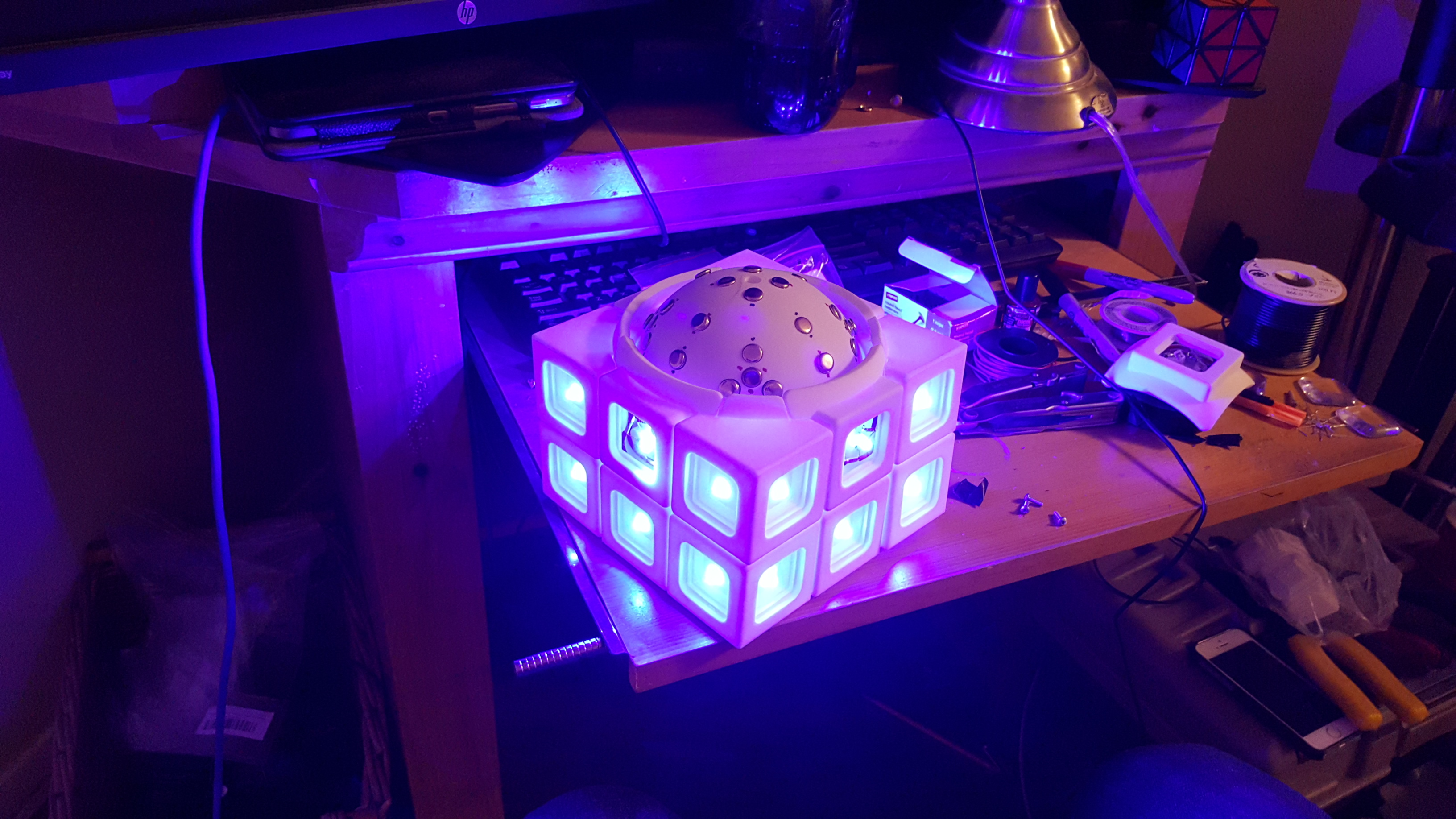
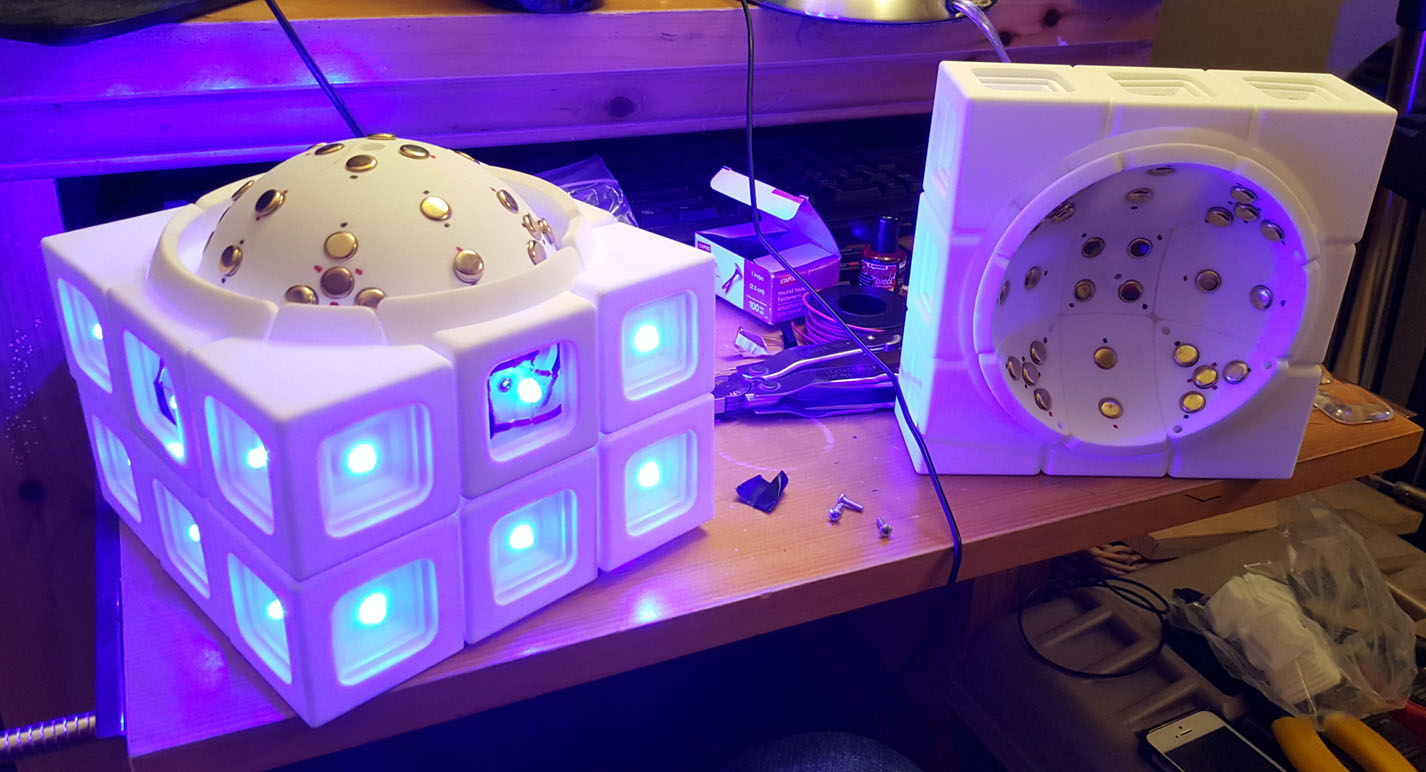
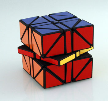
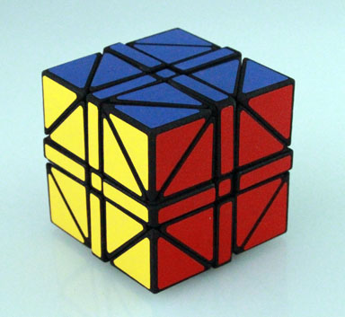
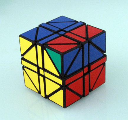
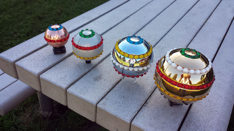
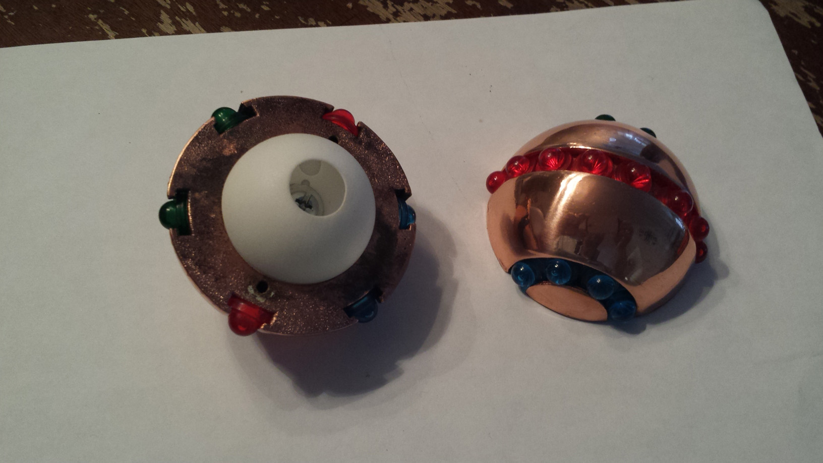
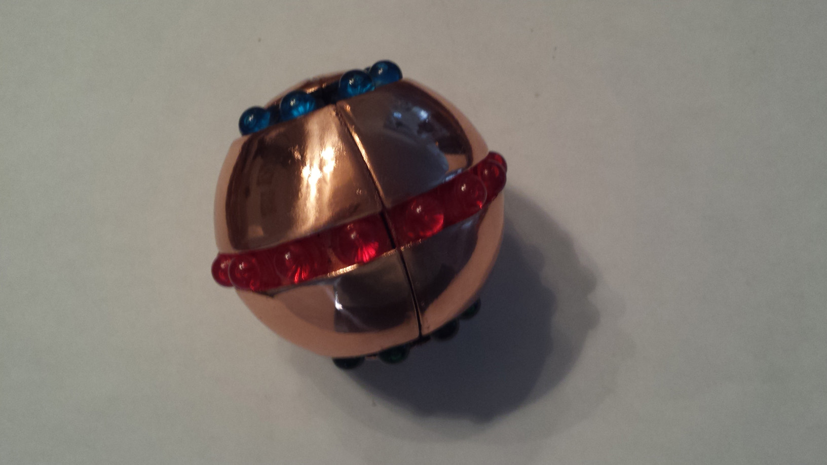
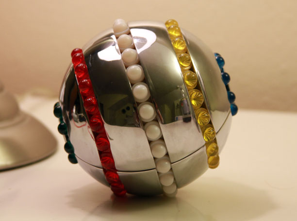
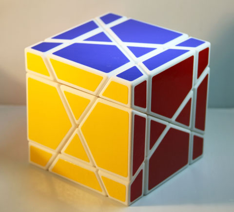
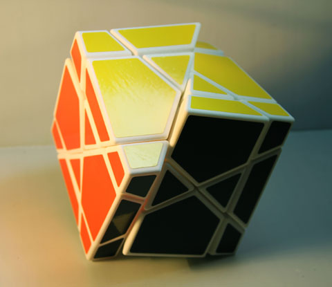
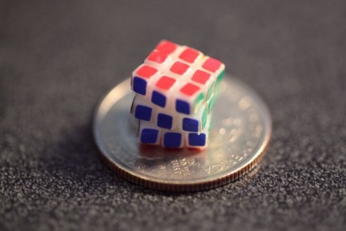
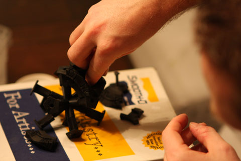
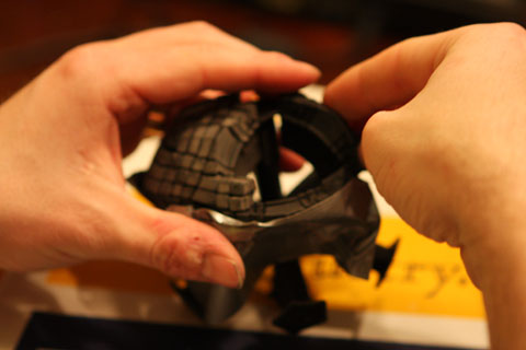
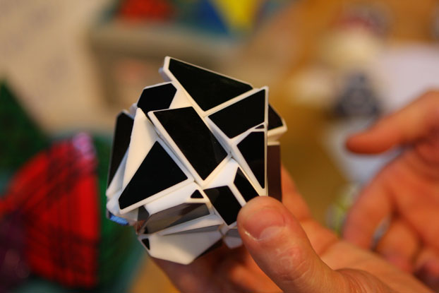
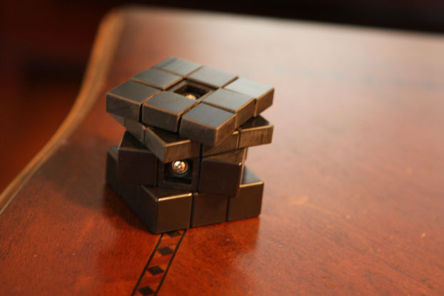
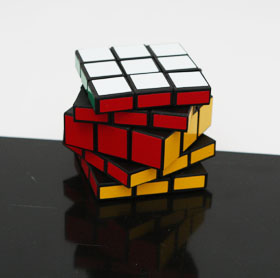
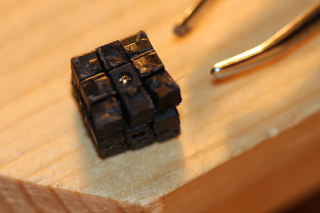
Each cubie has lights on the faces behind glass tiles. Upon the turn of a face, the cubies on that face toggle between on and off. I think the video will help make the idea clear.
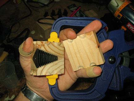
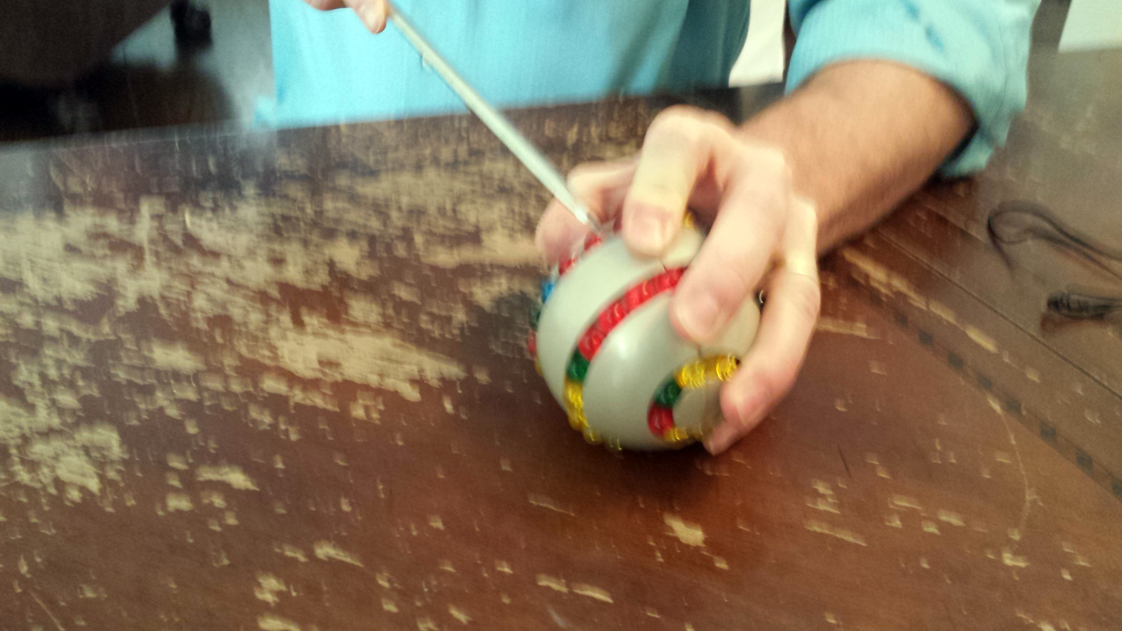
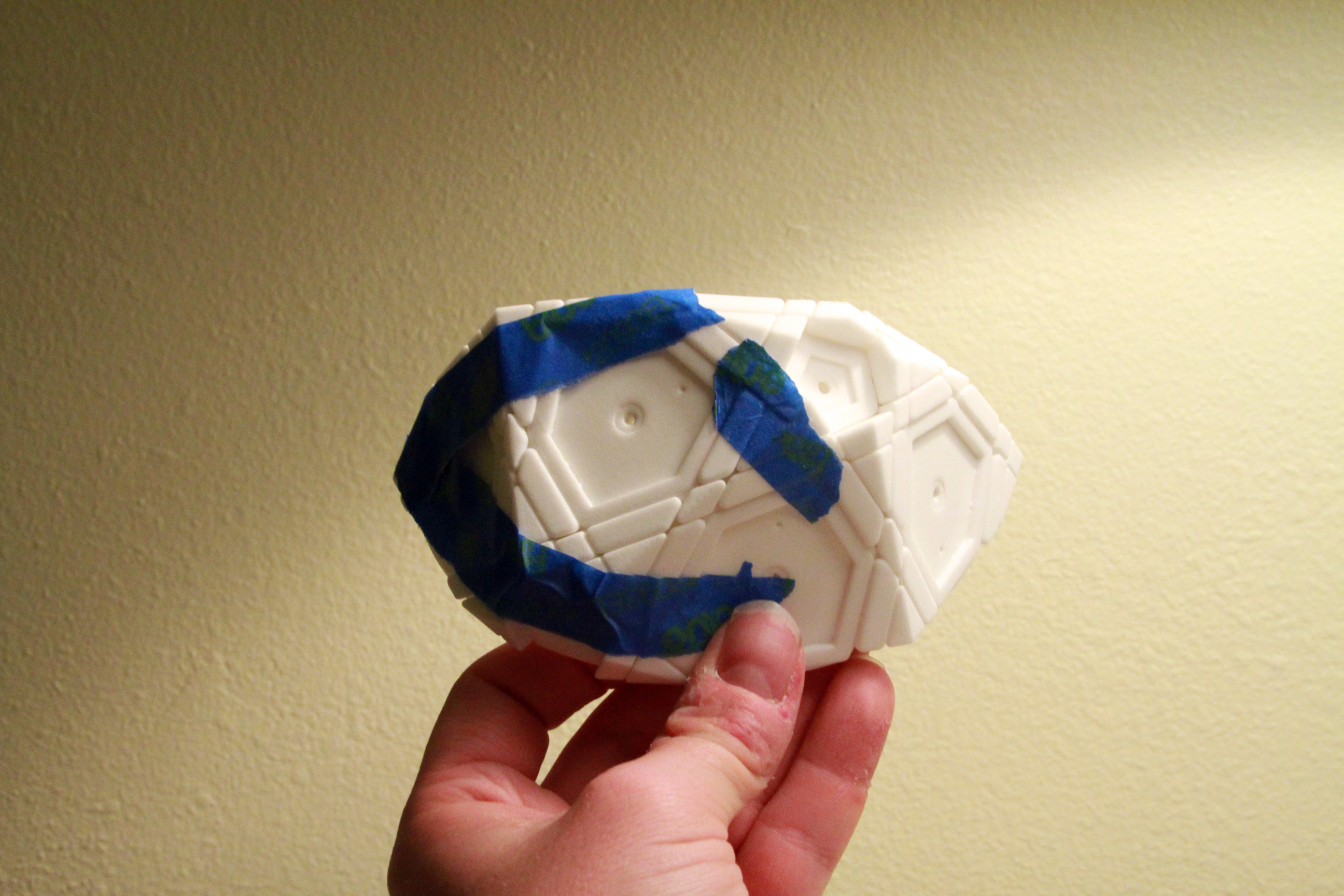
Photographing these bright LEDs with digital cameras is challenging, so please excuse the clamping.
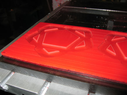
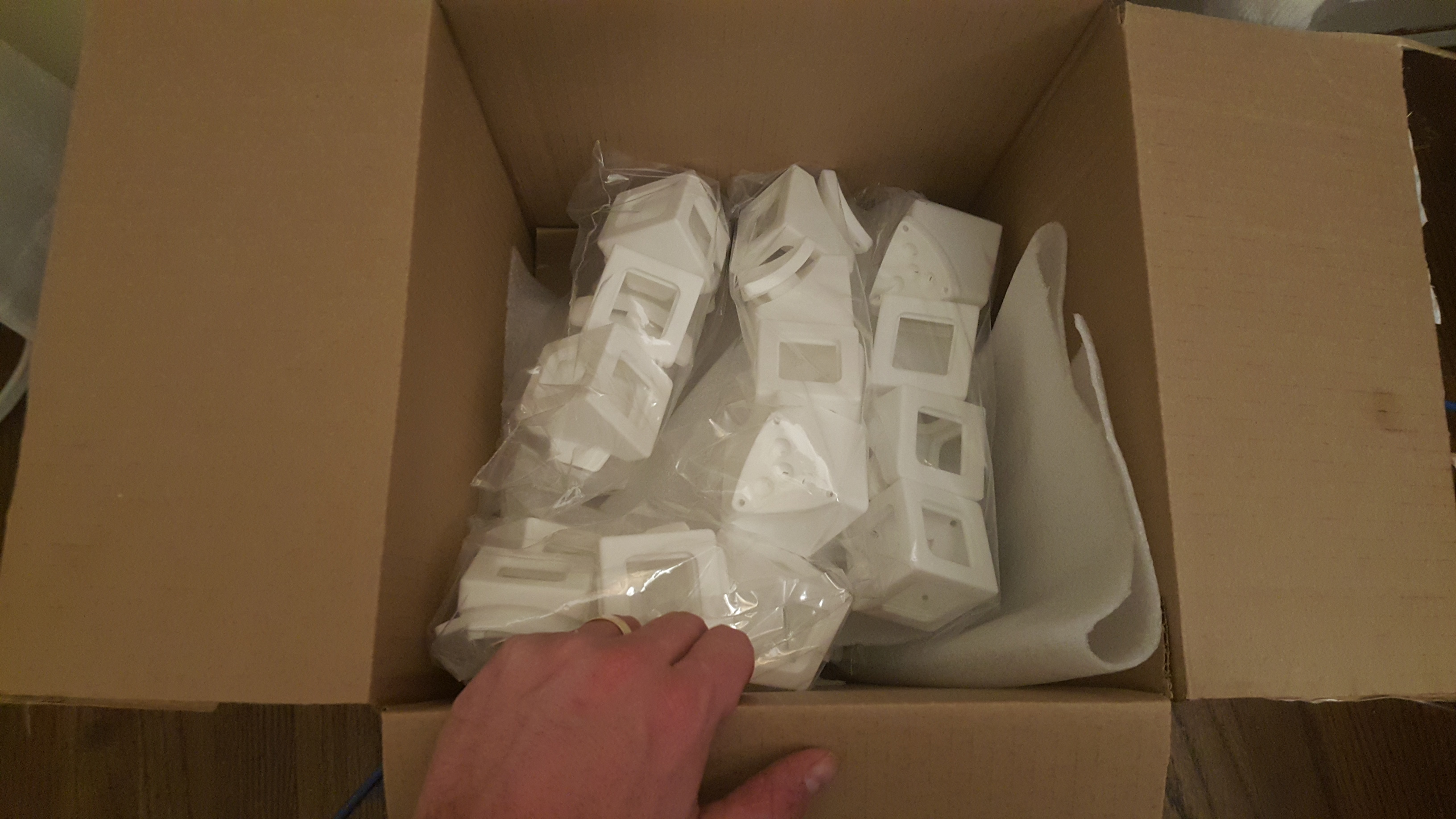
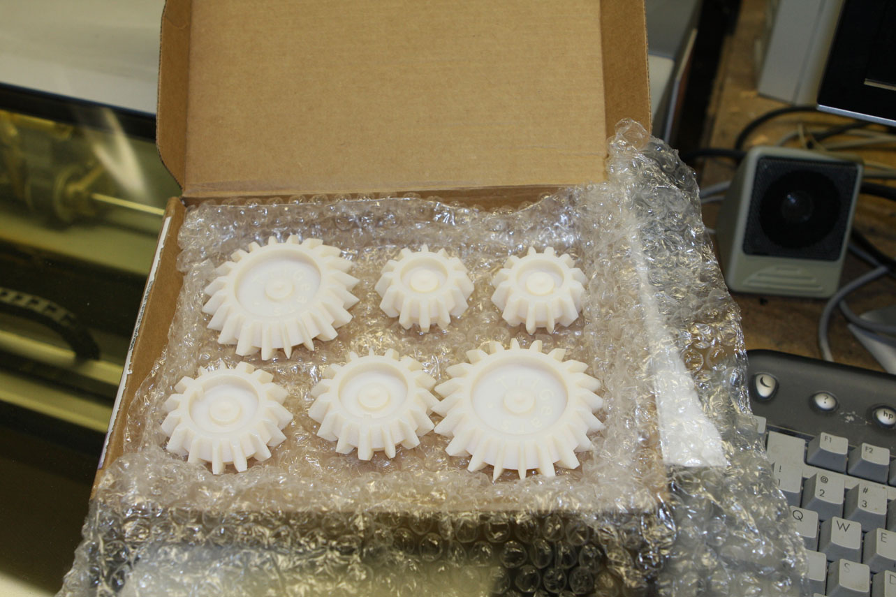
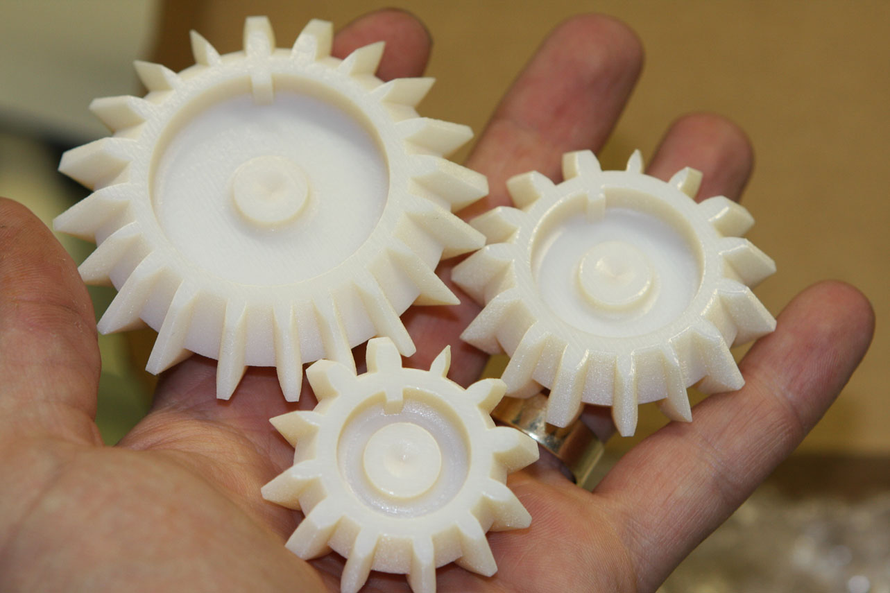
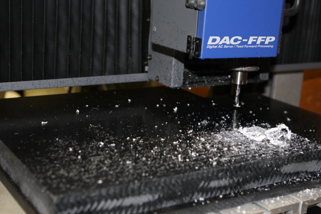
iMaterialise did a great job on the print.
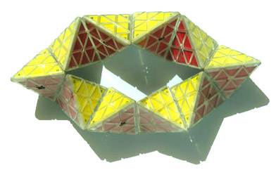
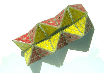
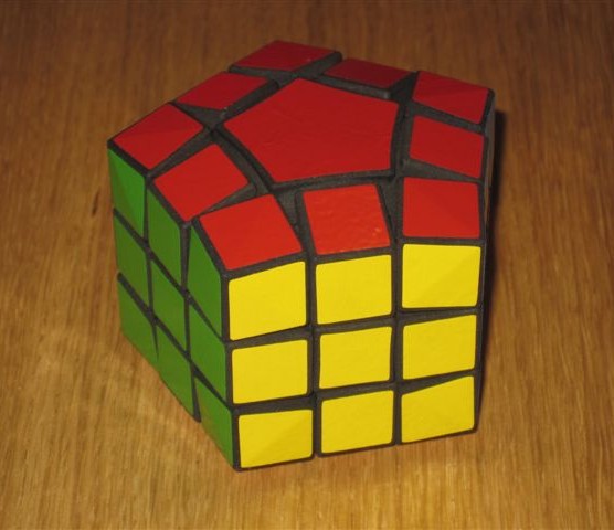
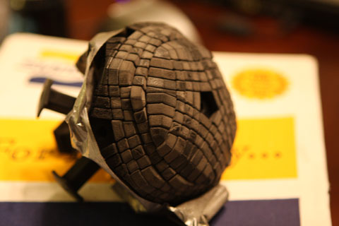
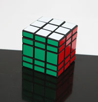
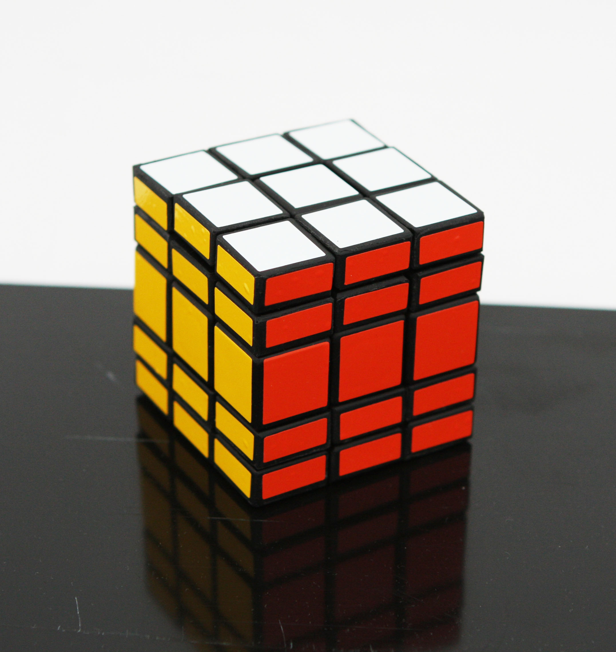
Can a fully ‘on’puzzle be solved into a fully ‘off’ state? – yes
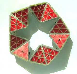
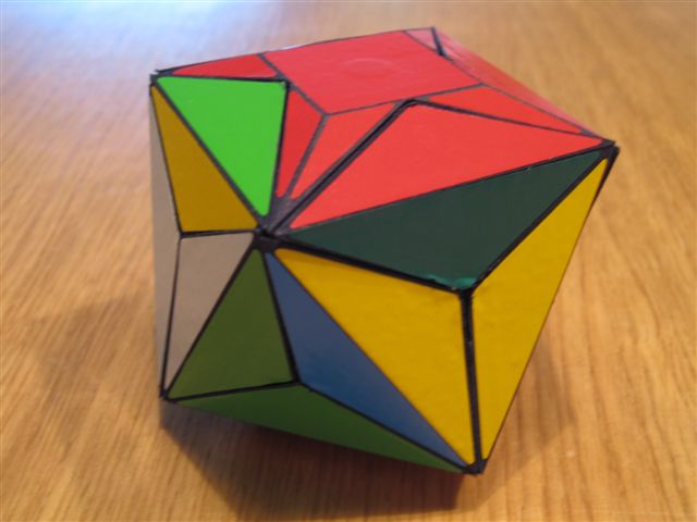
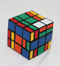
What does a checkerboard pattern look like? – unchanged
Making the Bit Box
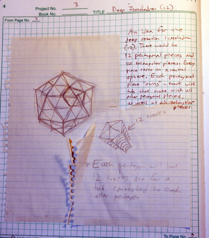
Version 0 – 2007
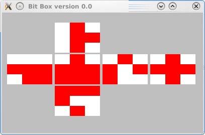
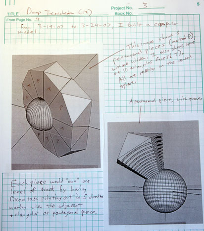
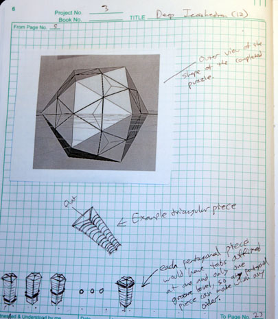
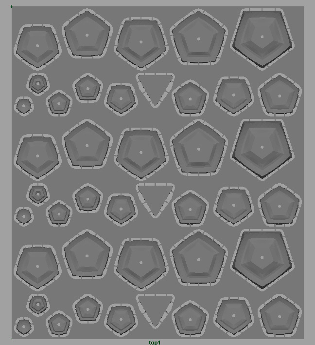
The Bit Box was first conceived in 2007. At that time, I modified xcube to simulate the idea.
It’s convenient that I used version 0.0 in the title bar when I did so!
During this time, I called this puzzle various names:
Binary Cube
Bit Box
Twist Off or Twiss’d Off
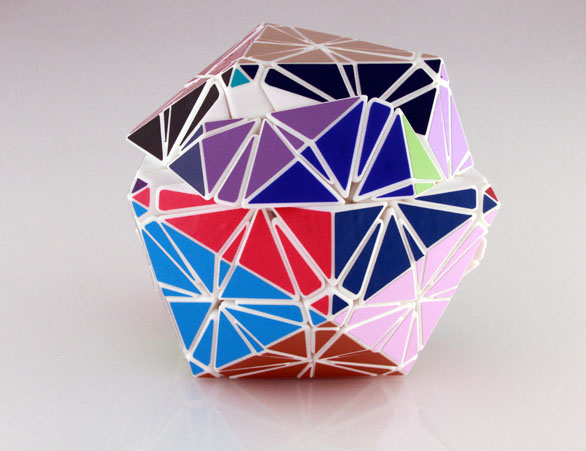
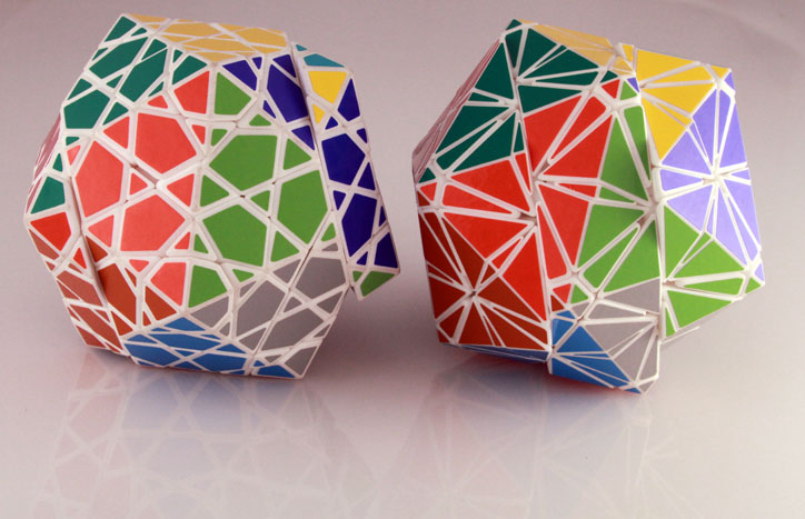
In the years from 2007 to 2013, I spent most of my puzzling time thinking about other projects like the Pentultimate, Petaminx, Radiolarian, etc. But I was always thinking and planning how one might be made. I had already considered the mechanical approach to making this puzzle, but the details were daunting.
It was clear that the usual approach of 3D printing everything could not apply here because of the electronics. I would need precise metal components to make the contacts work.
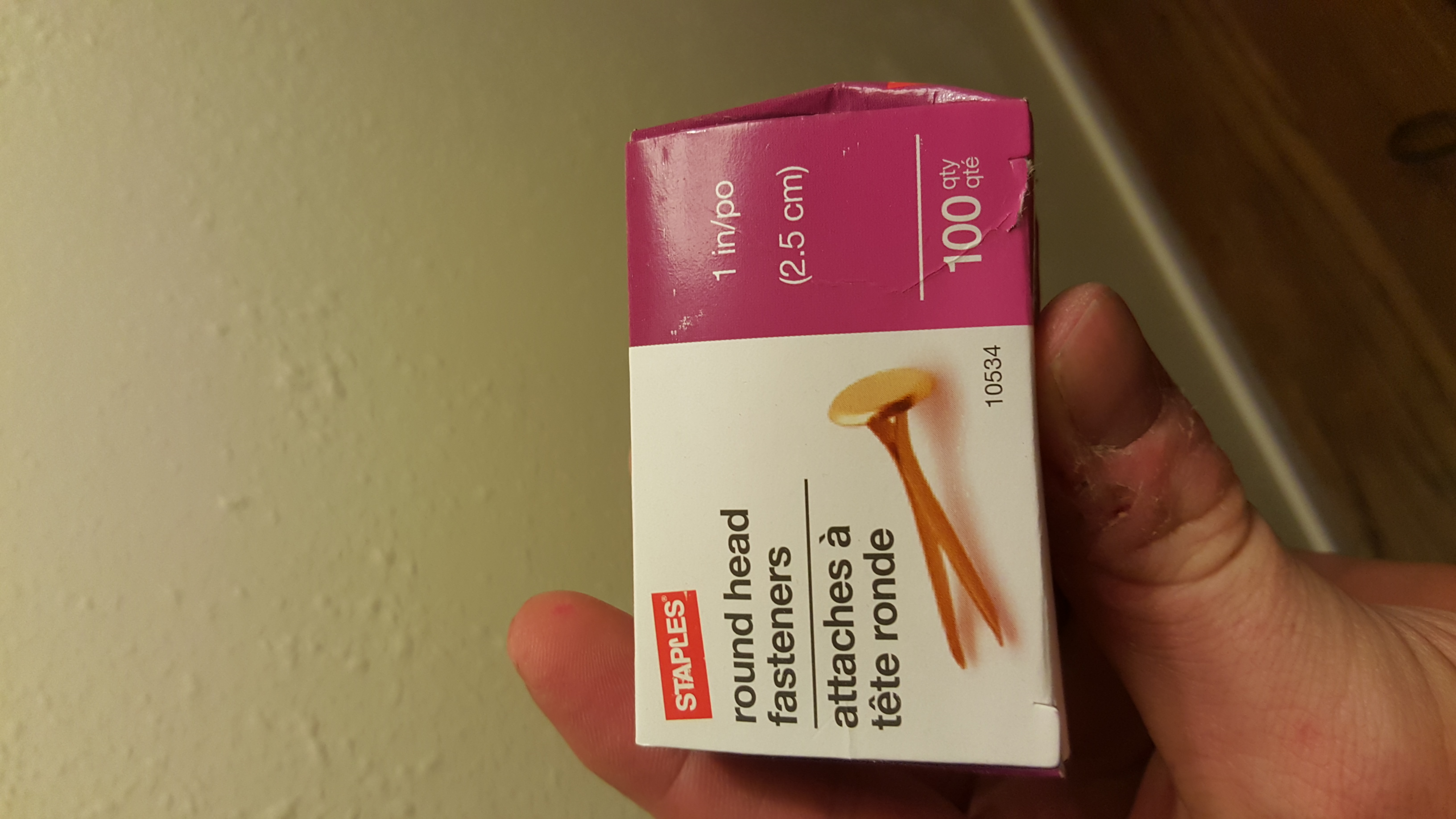
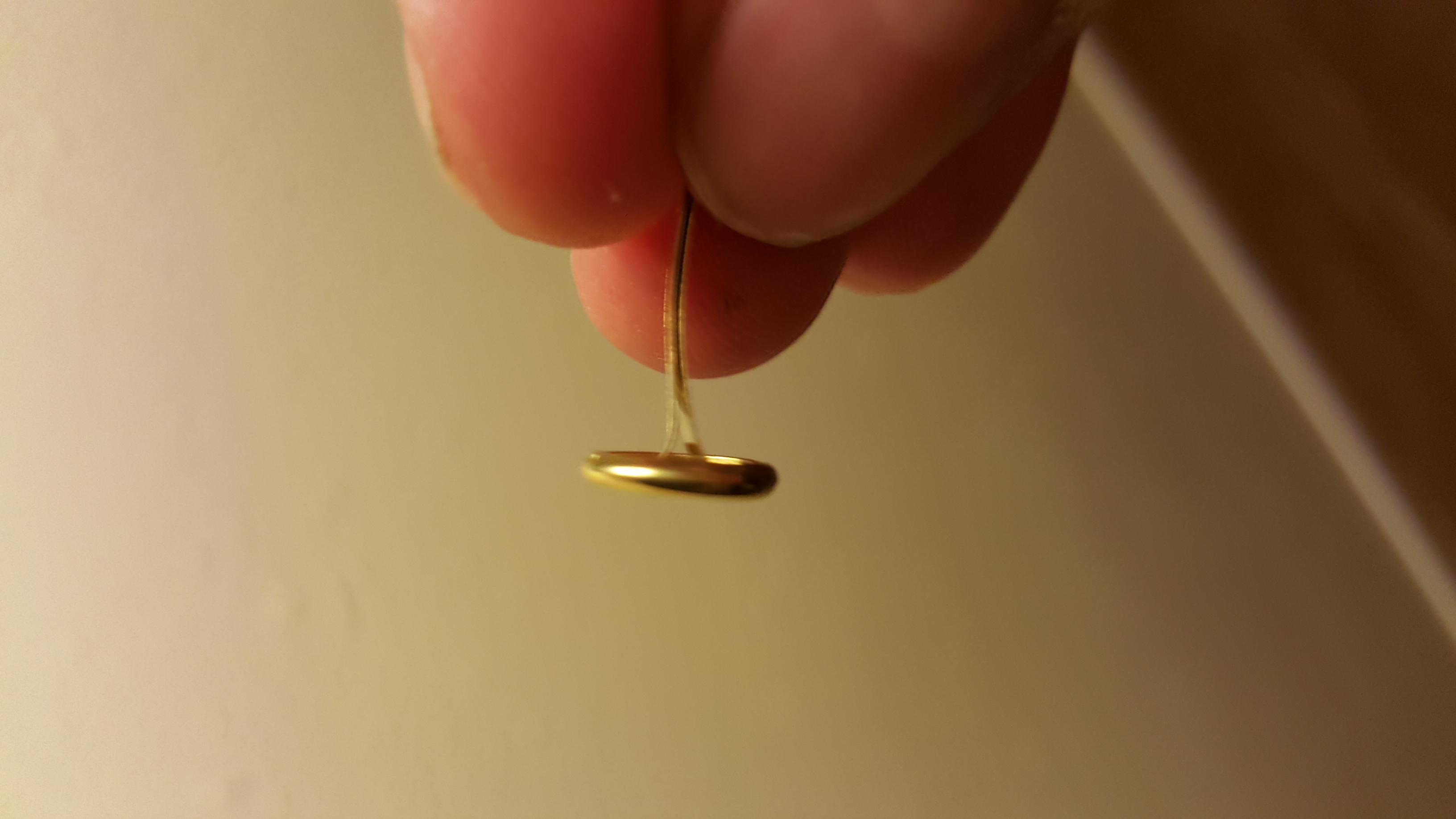
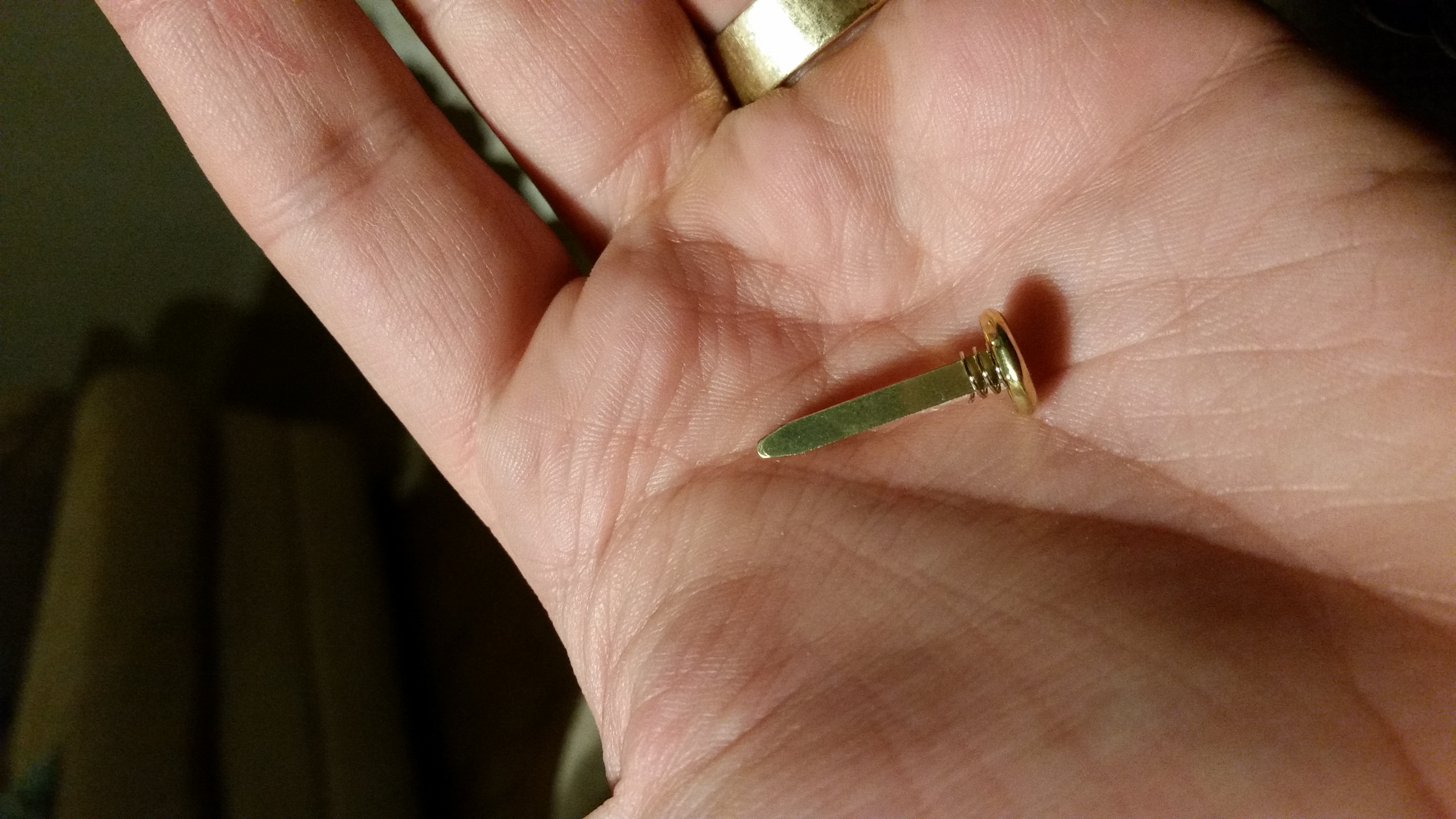
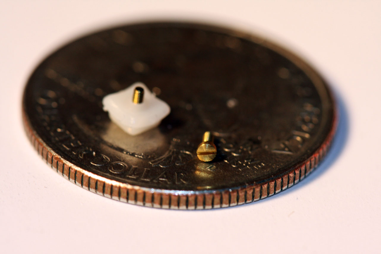
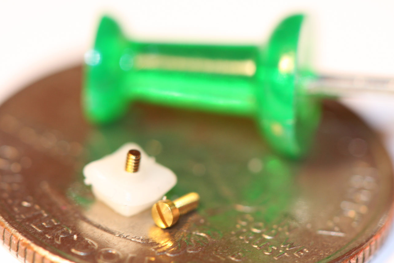
I needed electrical contacts with a built-in fillet, so that the contacts would not cause lockups. After a few months considering this problem between projects, I decided that brass brads could be used for the electrical contacts. They have round heads with rounded edges, and conduct electricity perfectly.
Version 1 – 2014
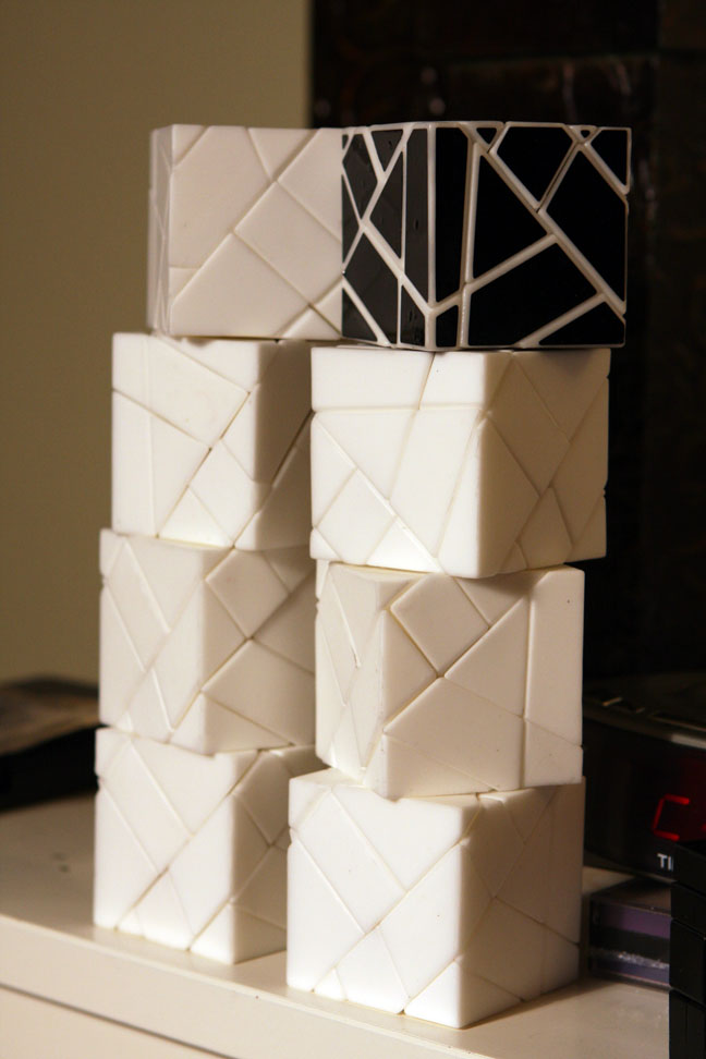
The first version of the BitBox was designed in April 2014. In most obvious ways, this design is almost identical to the final working puzzle.
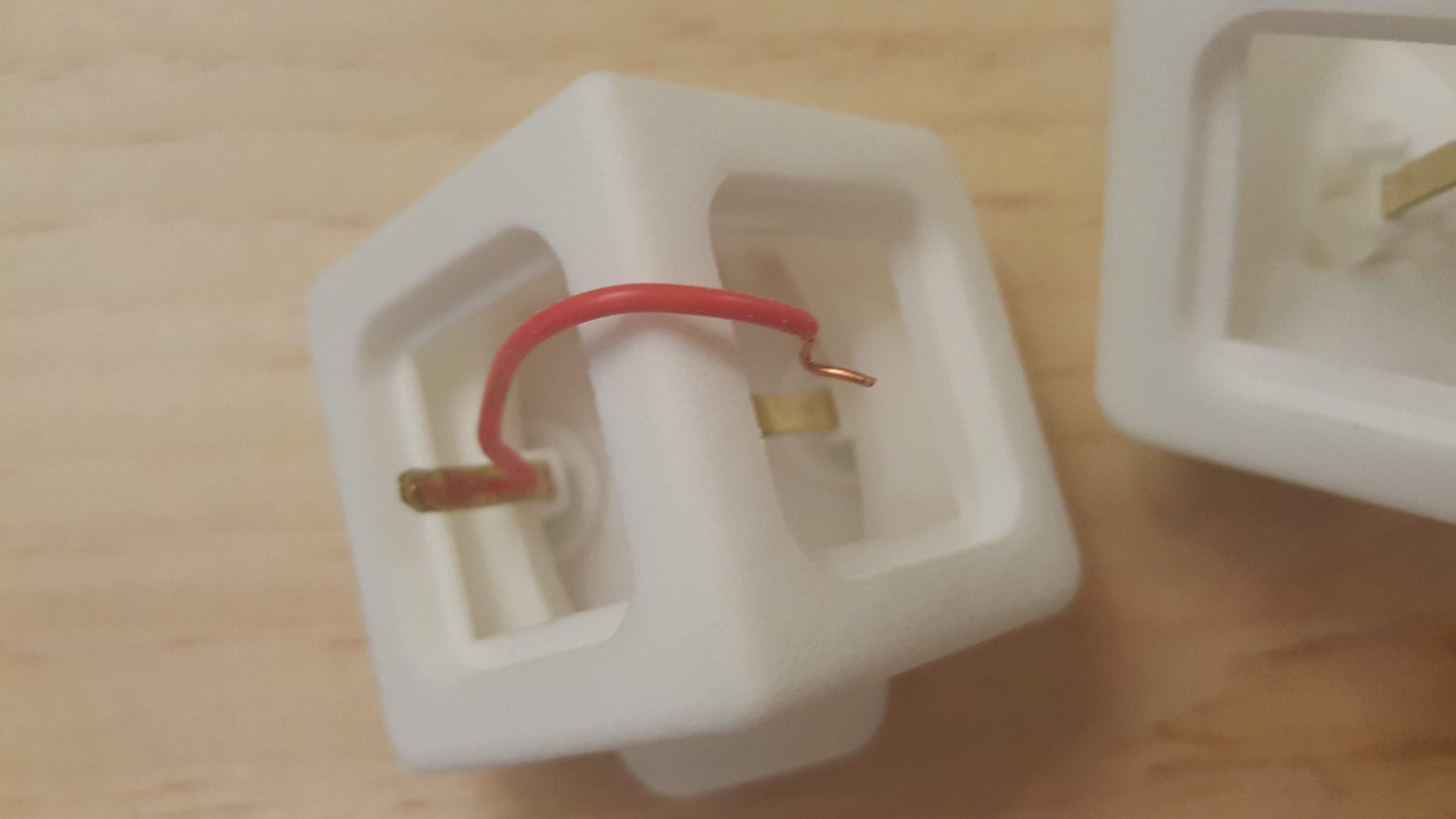
The main, defining problem in this version of the puzzle was that the edges and corners were too hard to assemble. In the edges, the brads had to turn a corner while being inserted:
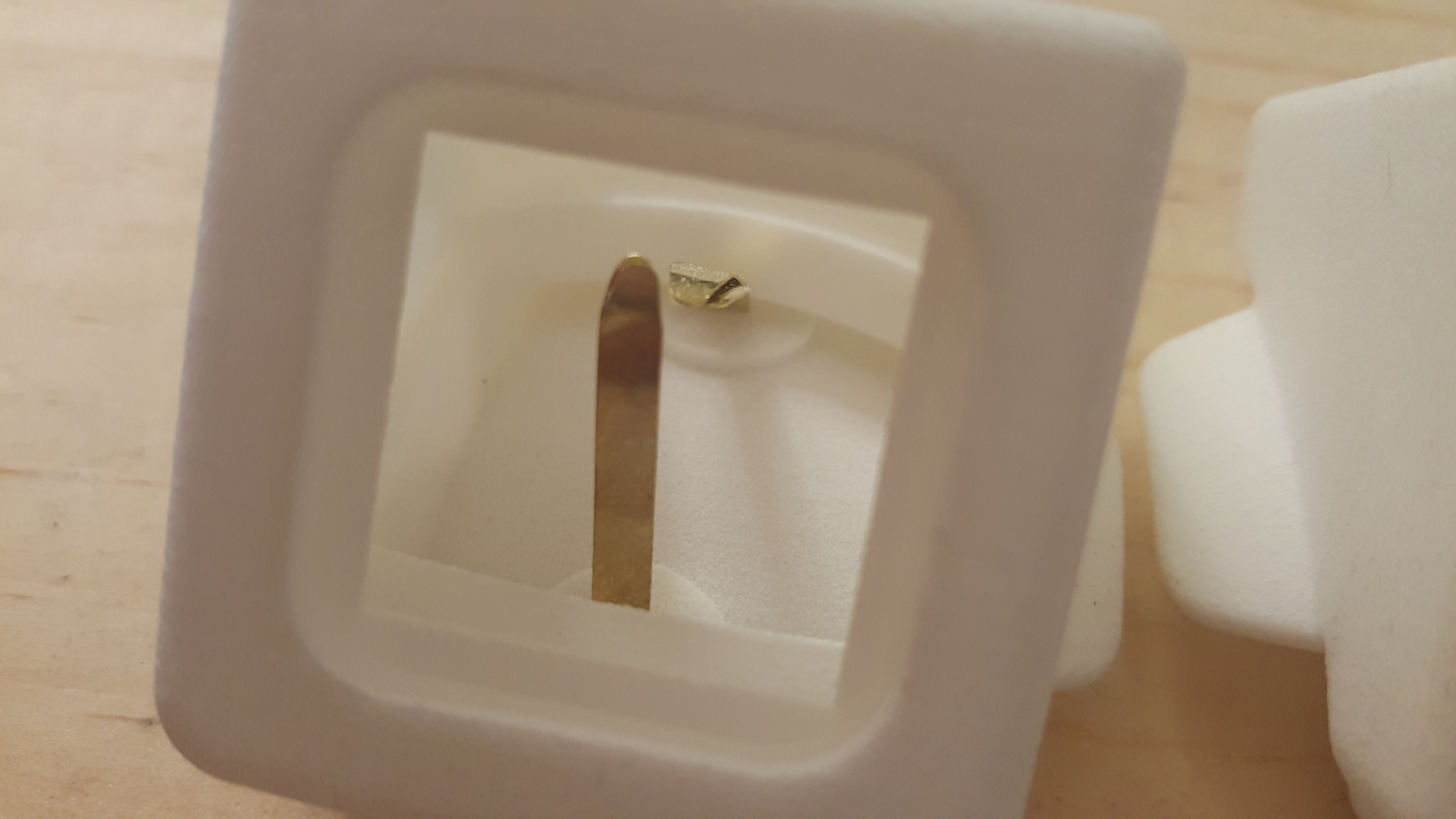
In some cases, I was able to get it to work, but it took a very, very long time. I was able to assemble one part every night in about three hours.,
At this point I started to worry.
The corners were even worse. One brad in the middle and three around it had to be inserted without touching each other. It took a long arduous fight to get each brad in. Paving the way for each brad destroyed multiple brads.
I was still able to make a few successful parts, but I had to use a lot of insulating tape, and again, each part took a long evening.
Version 2 – 2014
The second version was designed to make inserting the brads easier
Tracks were added to the brad holes to guide the brads around corners and into the interior of the part.
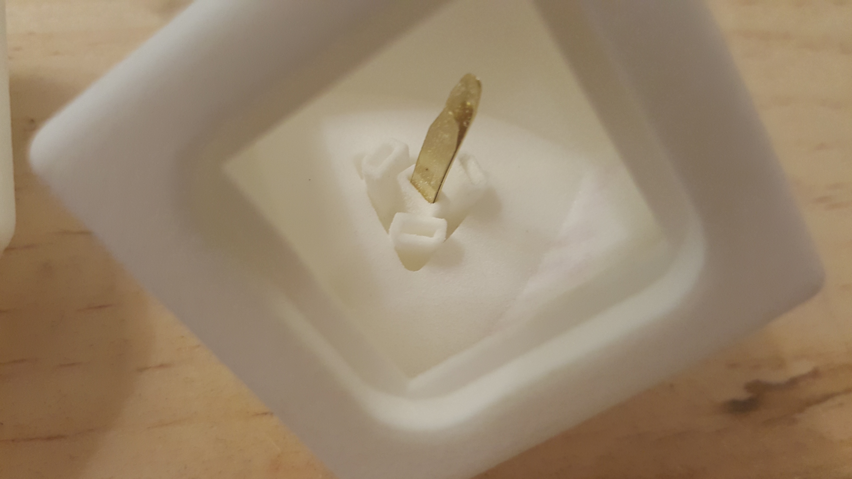
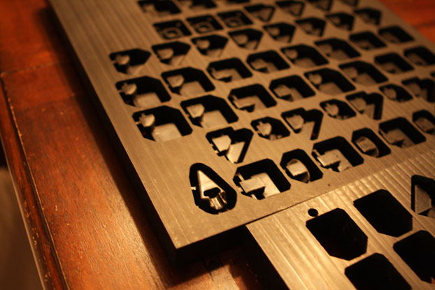
They were added to the edge, but ended up too tight to use: (click for a closer view)
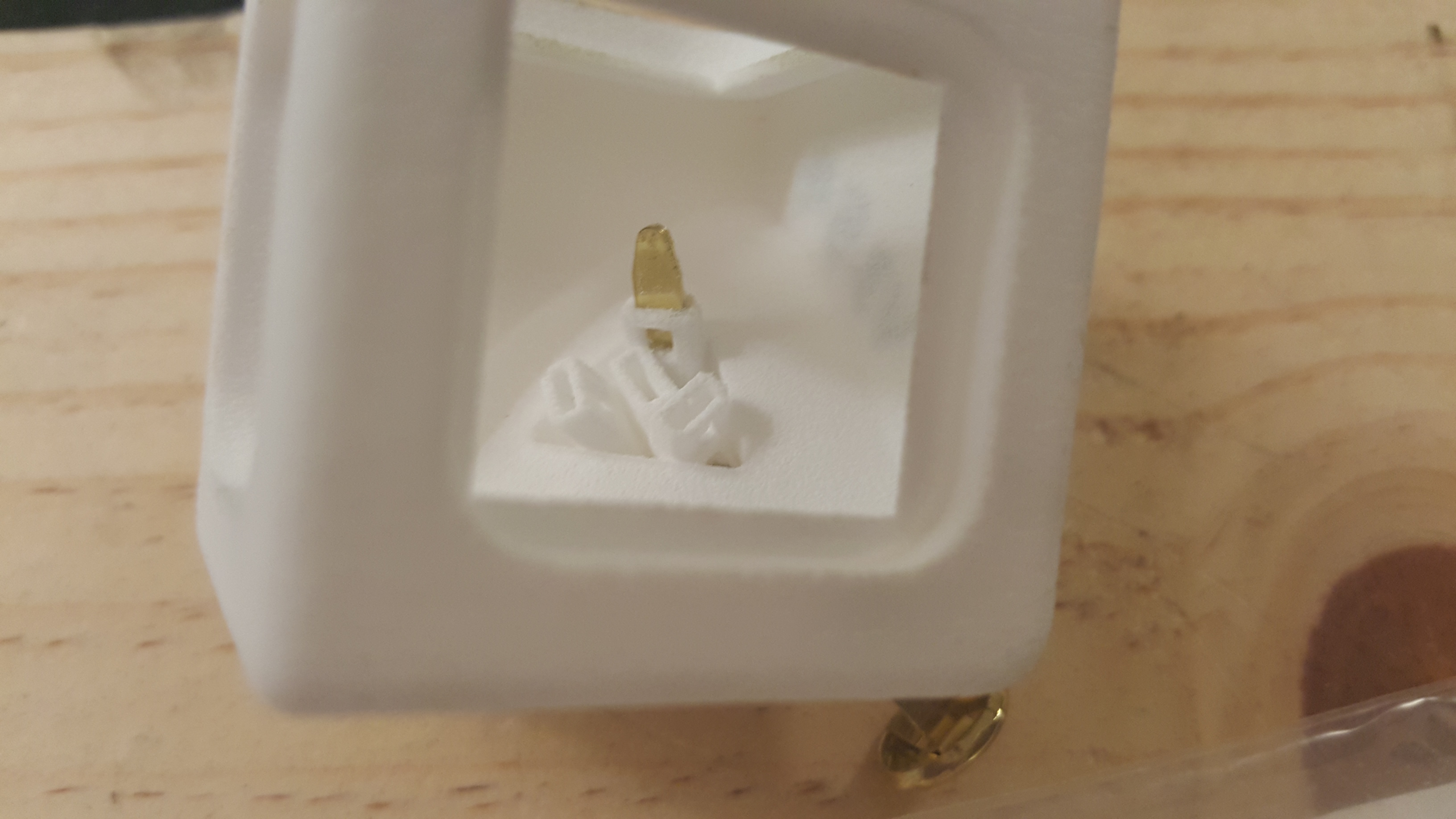
They were also added to the corner: (click for a closer view)
The corner was completely unusable. Brads couldn’t even be forced in.
Version 3 – 2014
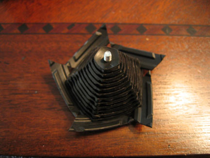
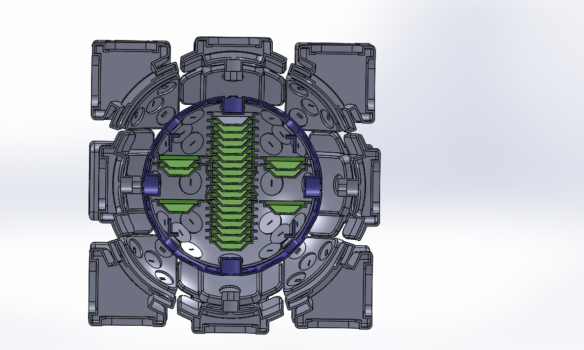
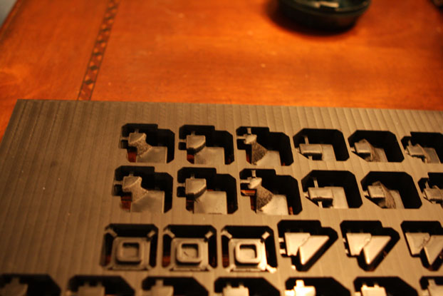
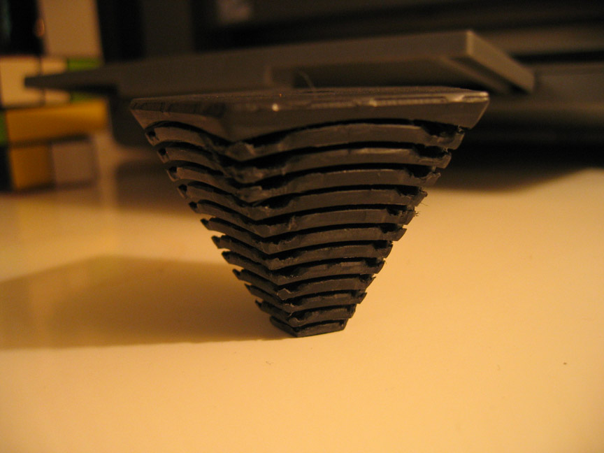
In the third version, the edges were finally usable. Here’s a section view showing the brad tracks.
Brads could be forced in without too much effort. I experimented with using the tracks to make electrical connections by forcing a wire in alongside, but it wasn’t a success.
The corners were also improved. The tracks were wider and included holes to help nylon powder escape.
In spite of the improvement, getting the brads in was still too labor intensive, with so much force required that they constantly bent.
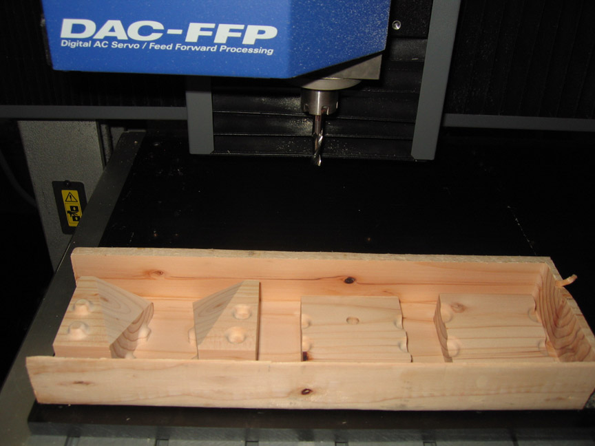
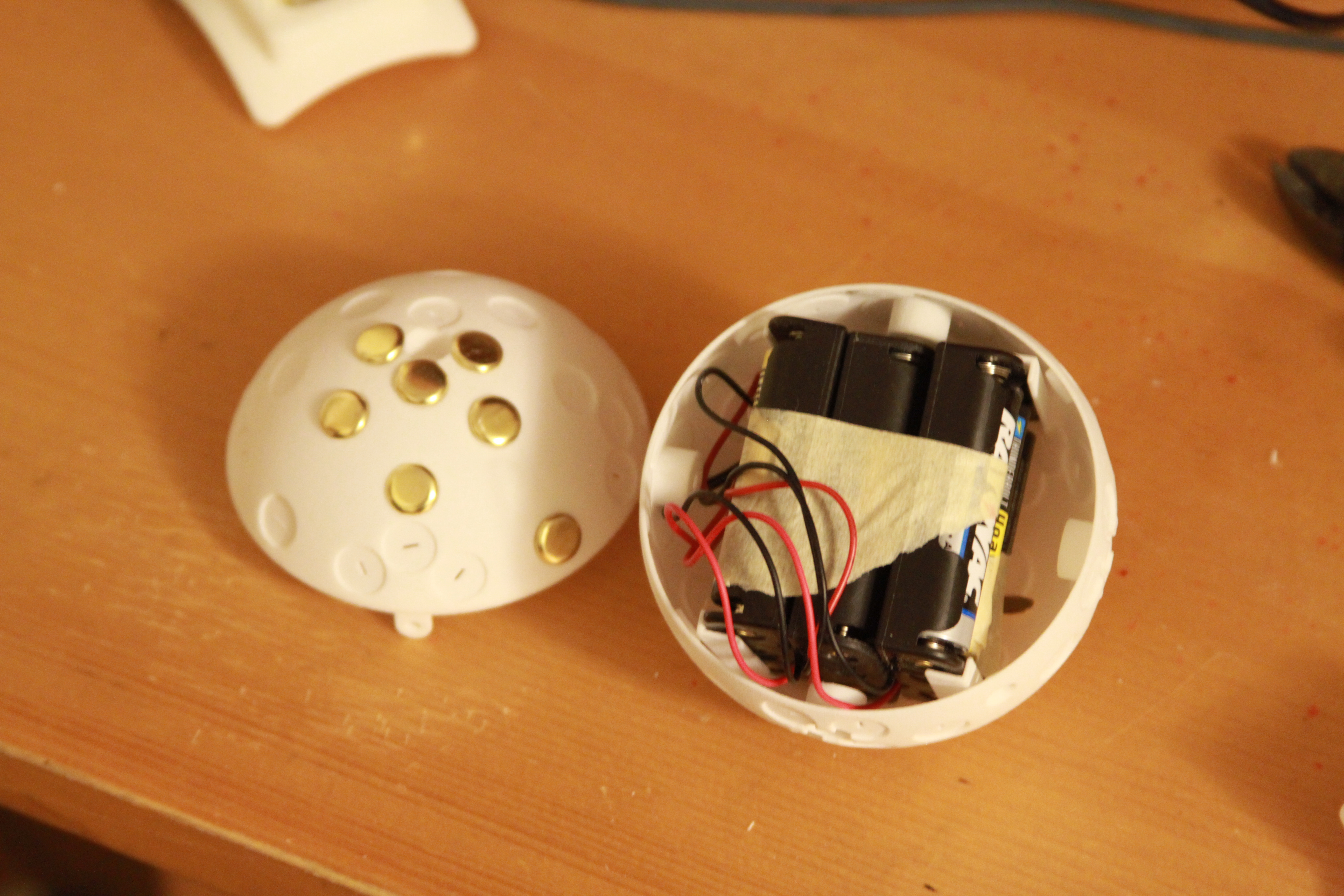
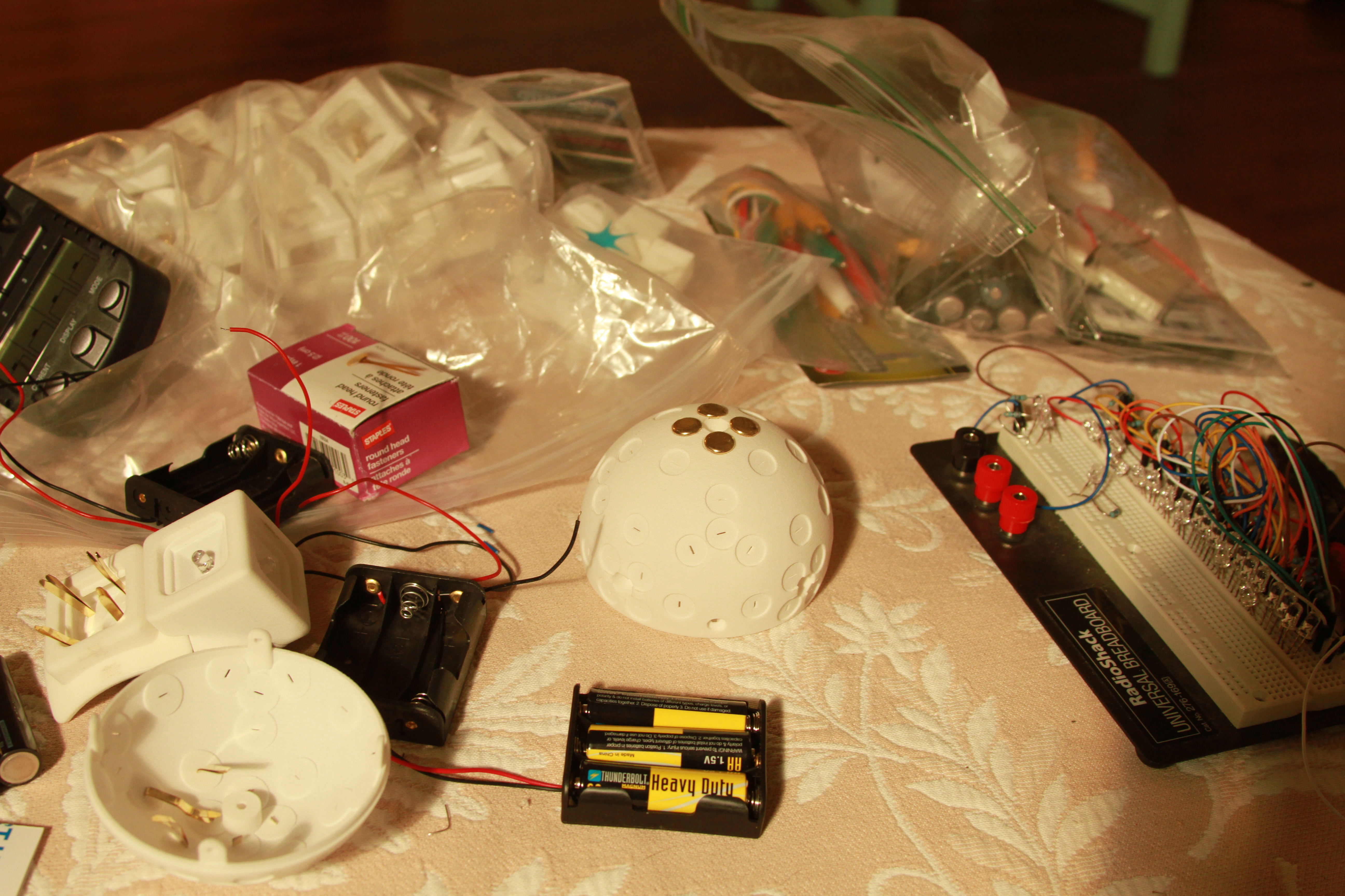
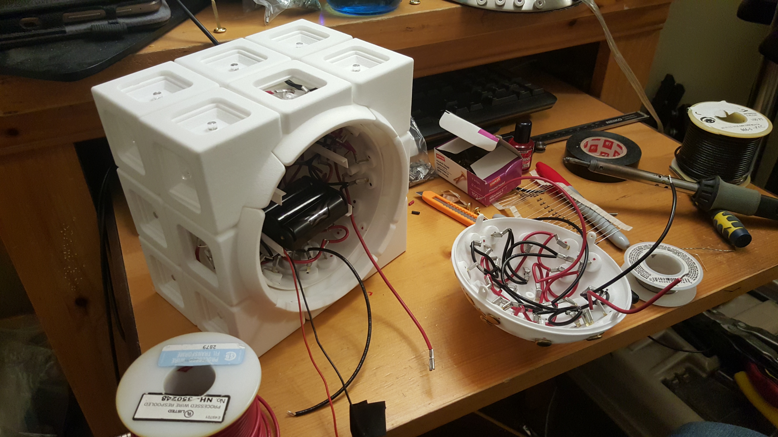
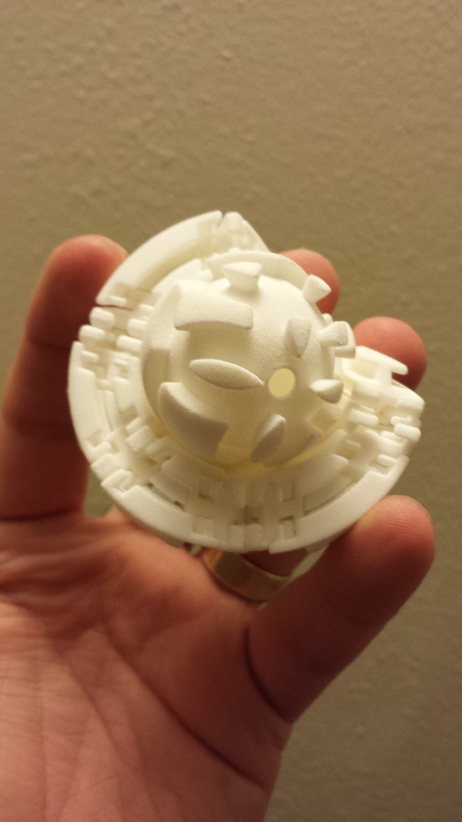
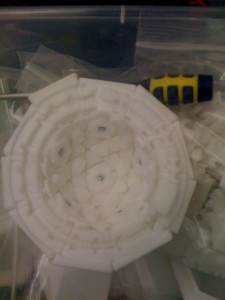
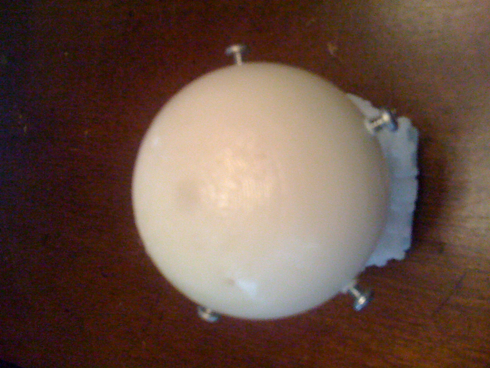
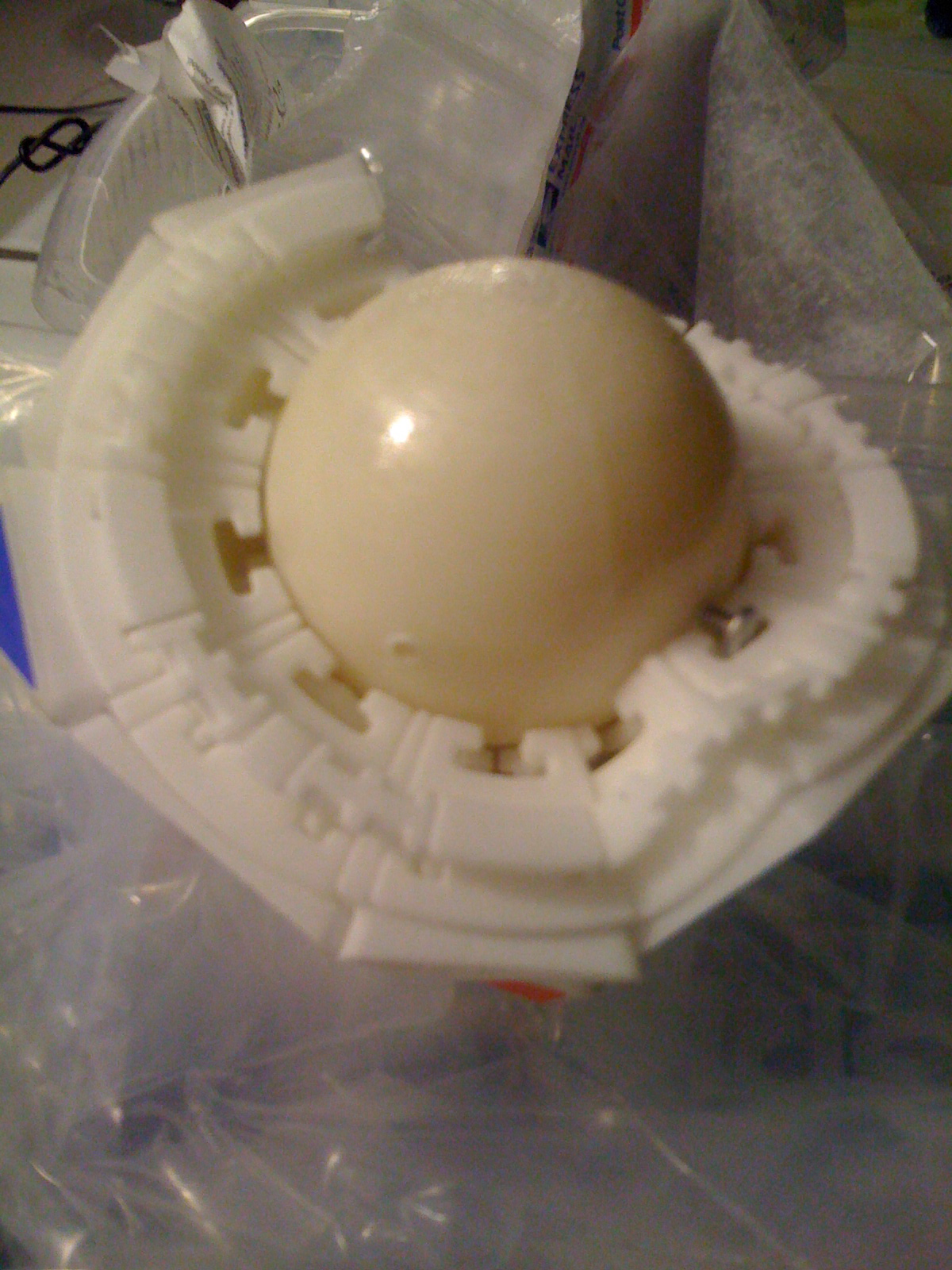
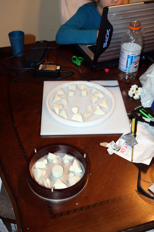
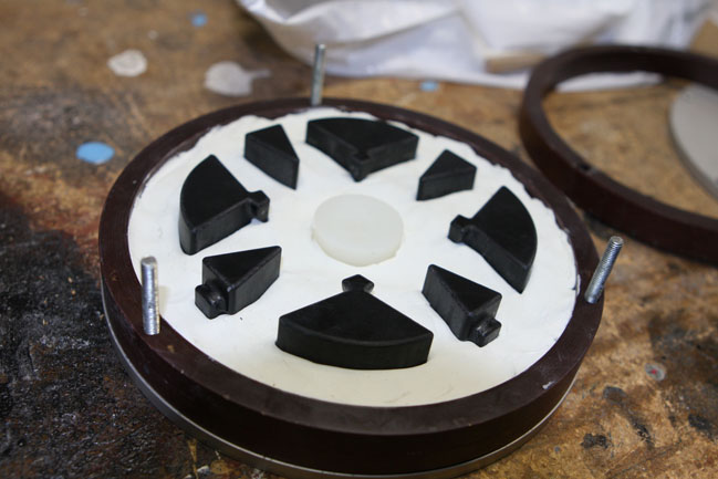
Even so, I was able to begin experimenting with assembly. I tested the fit of the battery pack in the core, which worked well.
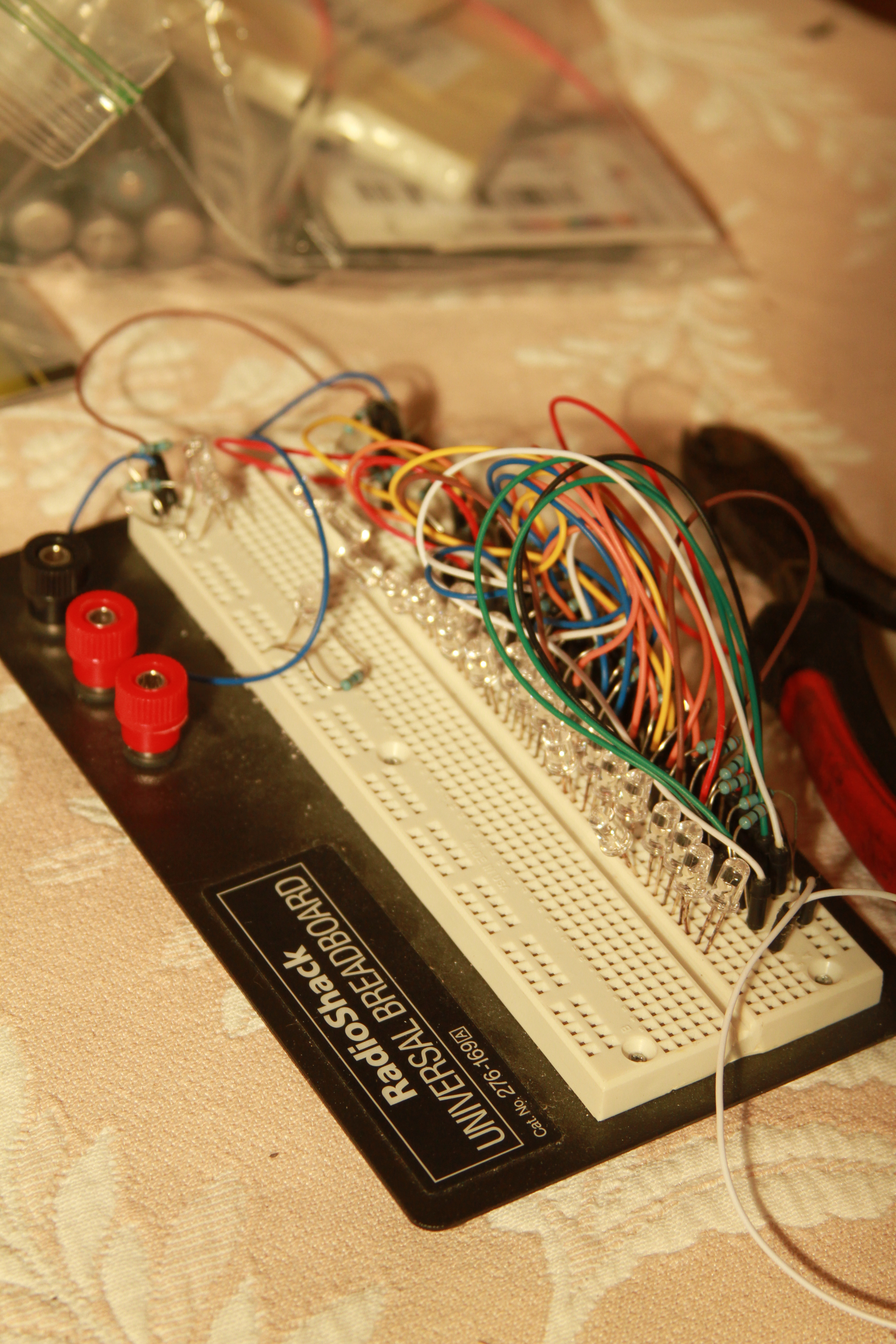
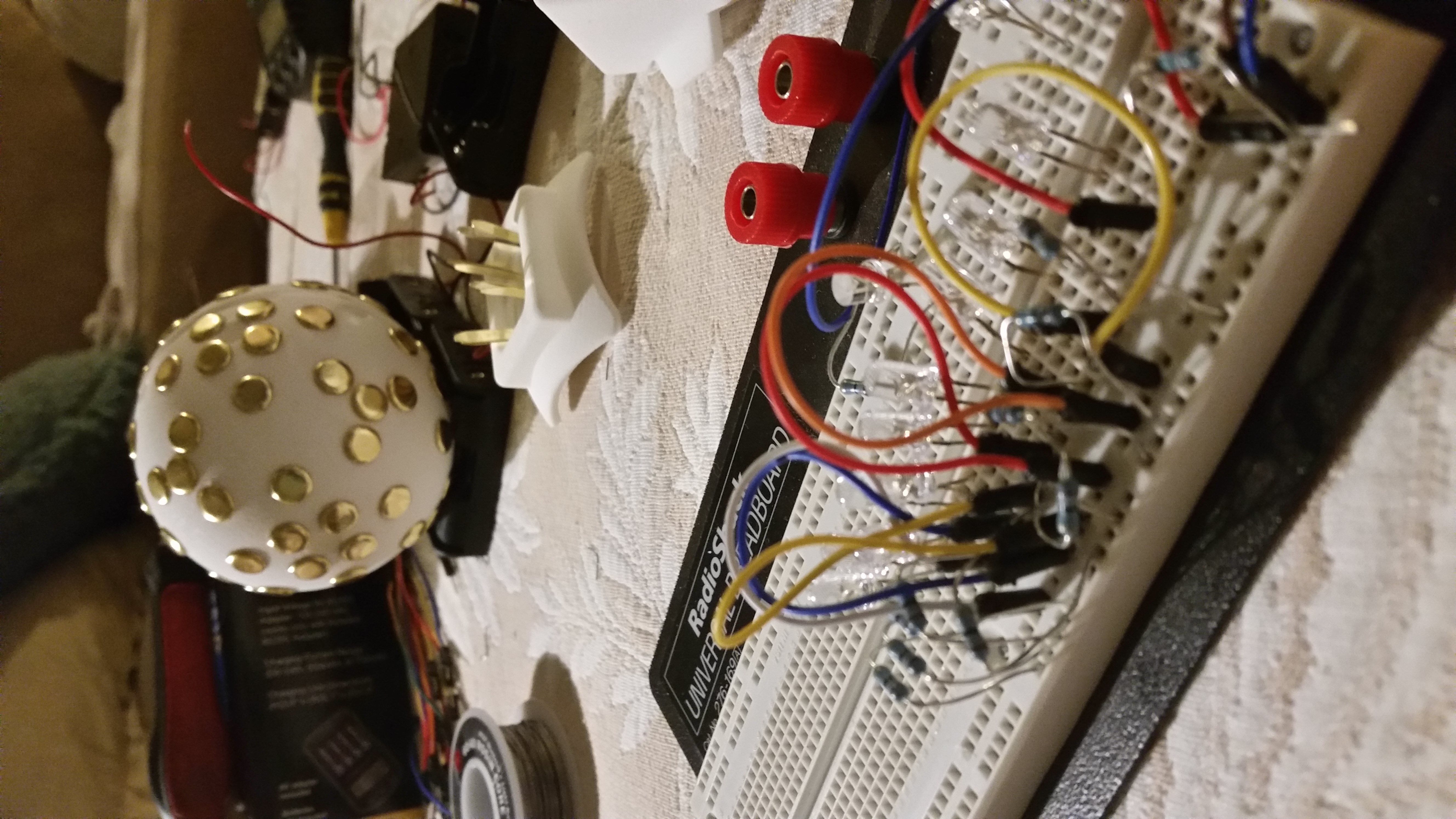
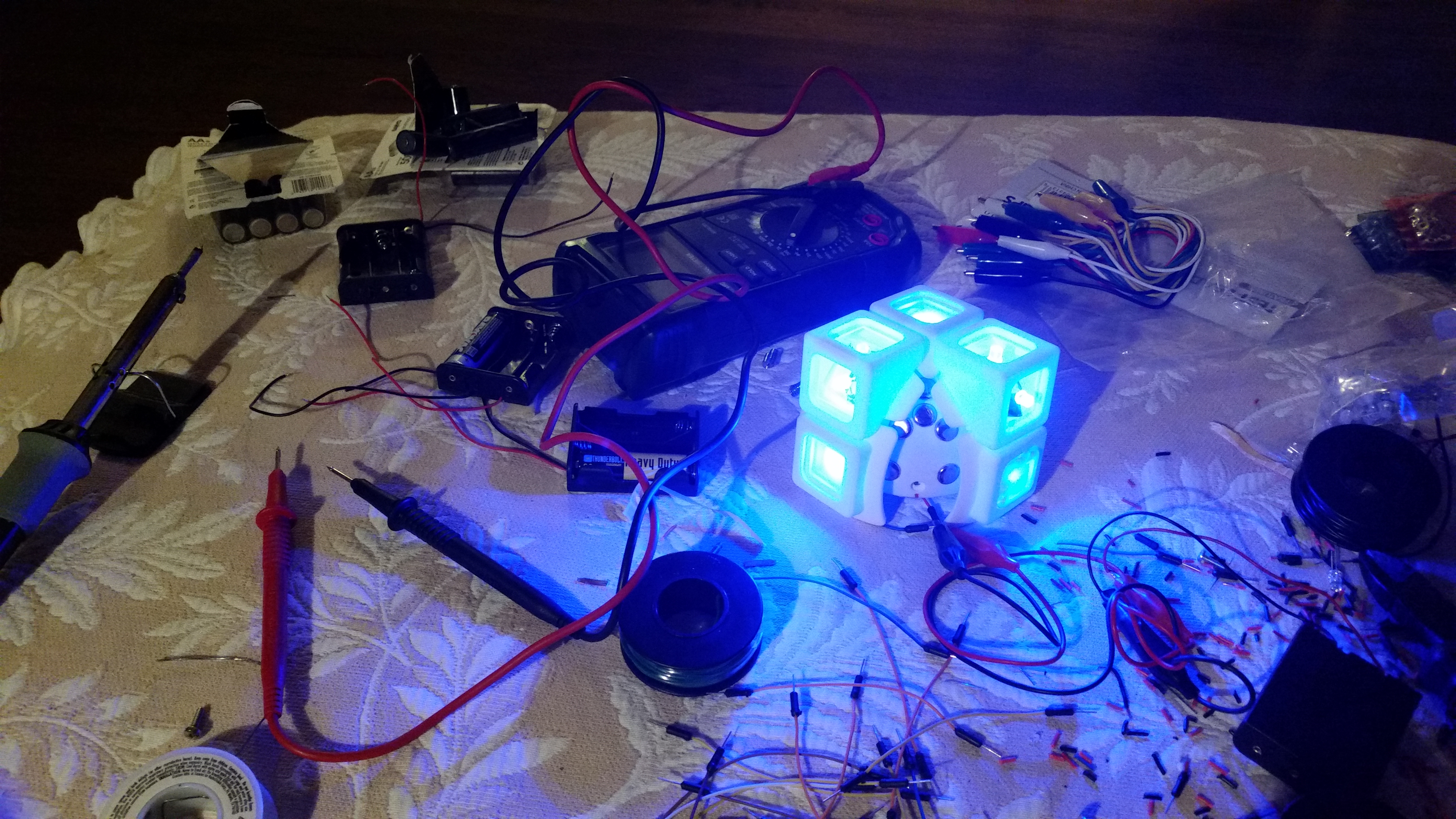
I also mocked up the planned electrical design on a breadboard to make sure that I could safely and successfully power all the LEDs.
I added the brads into the core, and began adding their electrical connections.
The entire puzzle was too loose. Even if I tightened the centers as much as possible, they still weren’t strong enough at holding in the edges to make a strong electrical contact. The more I tried to make the edge contacts tighter, the more the edges lifted up the centers from their contacts.
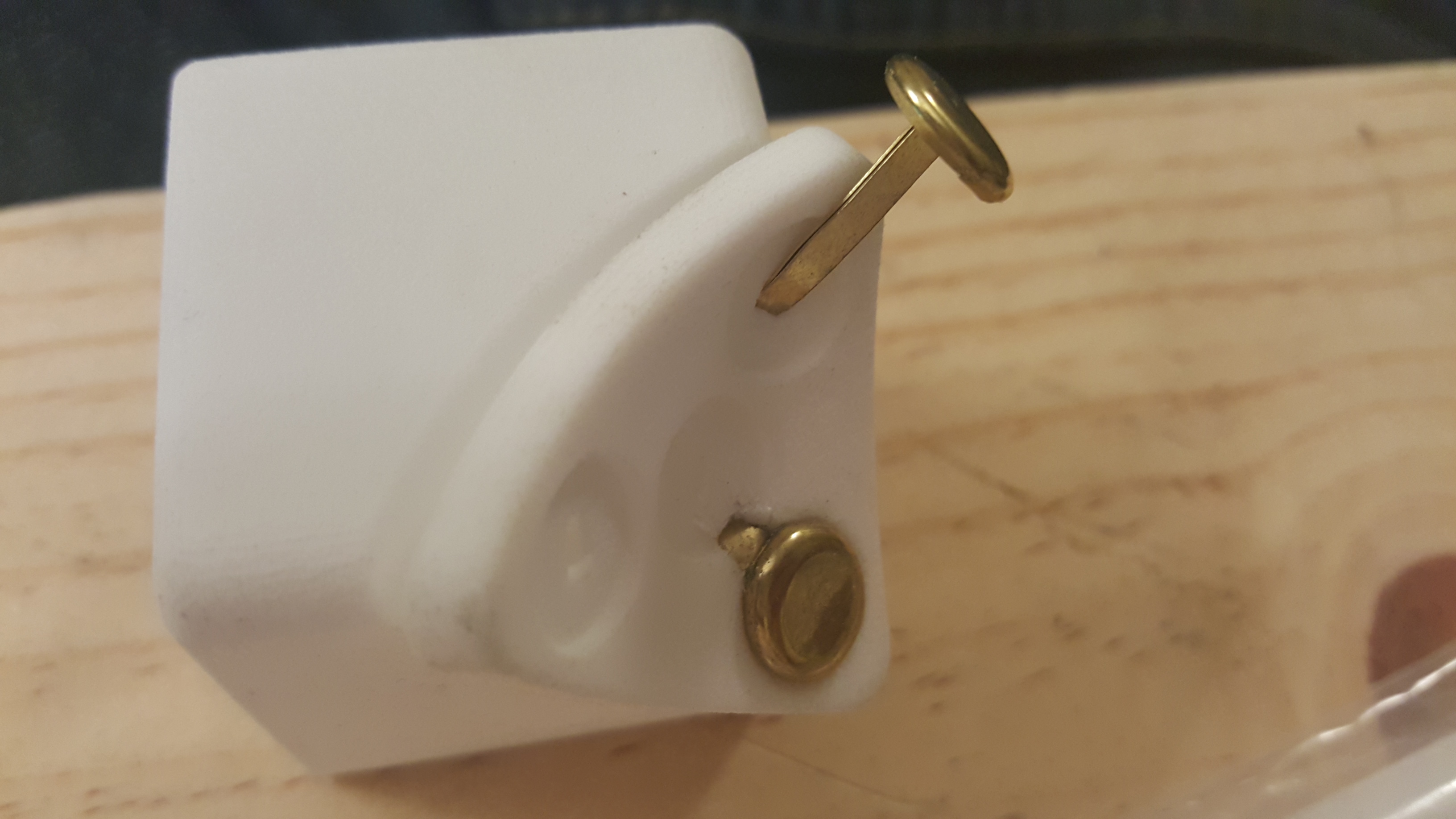
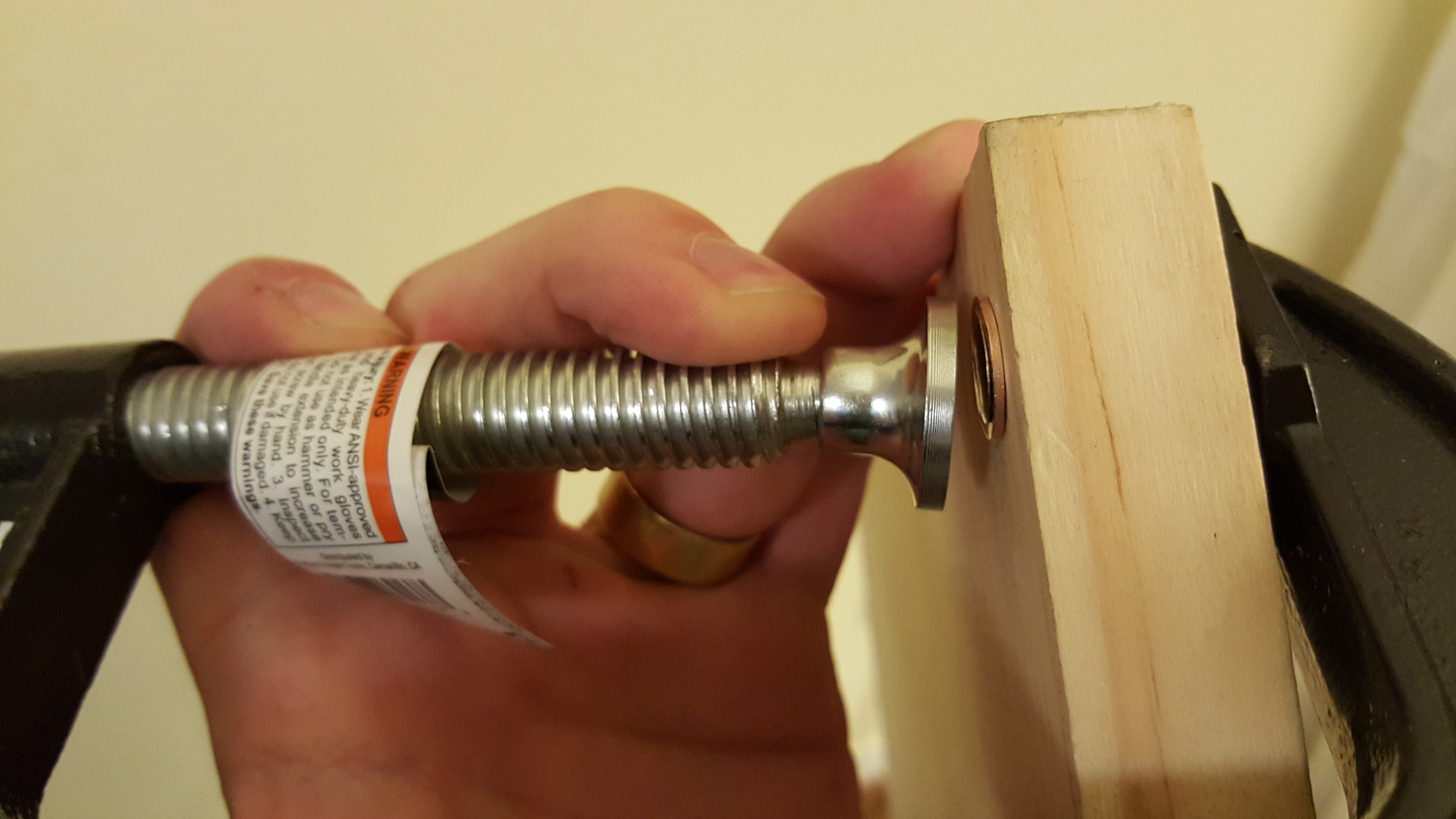
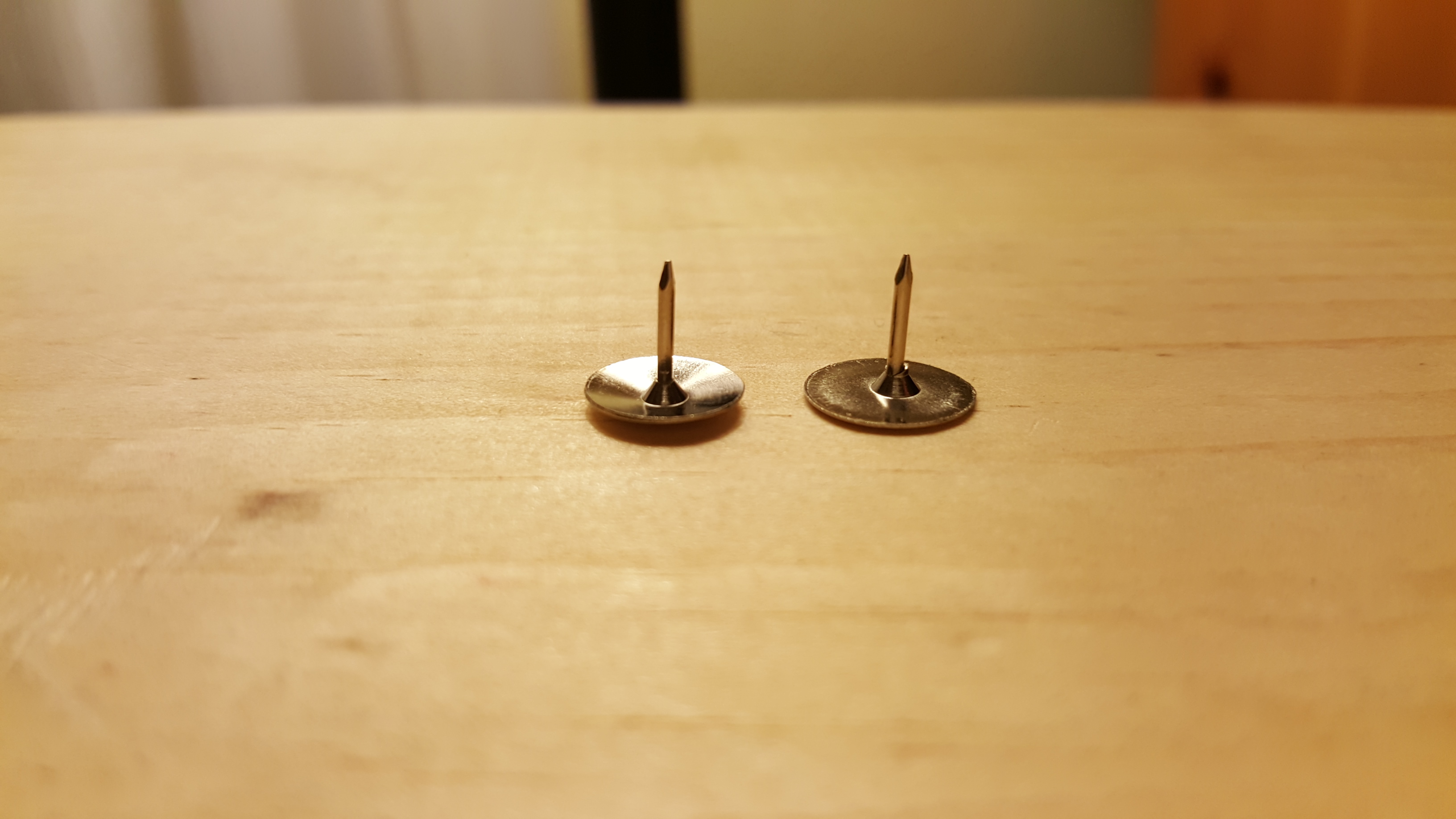
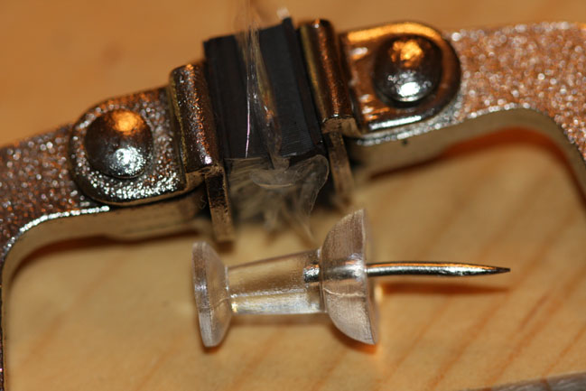
I tried to make the corners fit closer to the core by switching from brass brads on the centers to nickel thumbtacks. In addition, the thumbtacks were clamped flat to make the centers even tighter.
Even that didn’t solve the problem, so I also added small springs to the brads on the edges to try to create some pressure on the connection and bridge the gap when it was too loose.
Using these techniques, I was able to get some parts to light up. Unfortunately, the more parts I added, the less likely it was that they would all make good contact. A very frustrating process of trying to make this work began at this point.
I made the decision at this point to redesign the core in order to make the centers, and thus the whole puzzle, tighter.
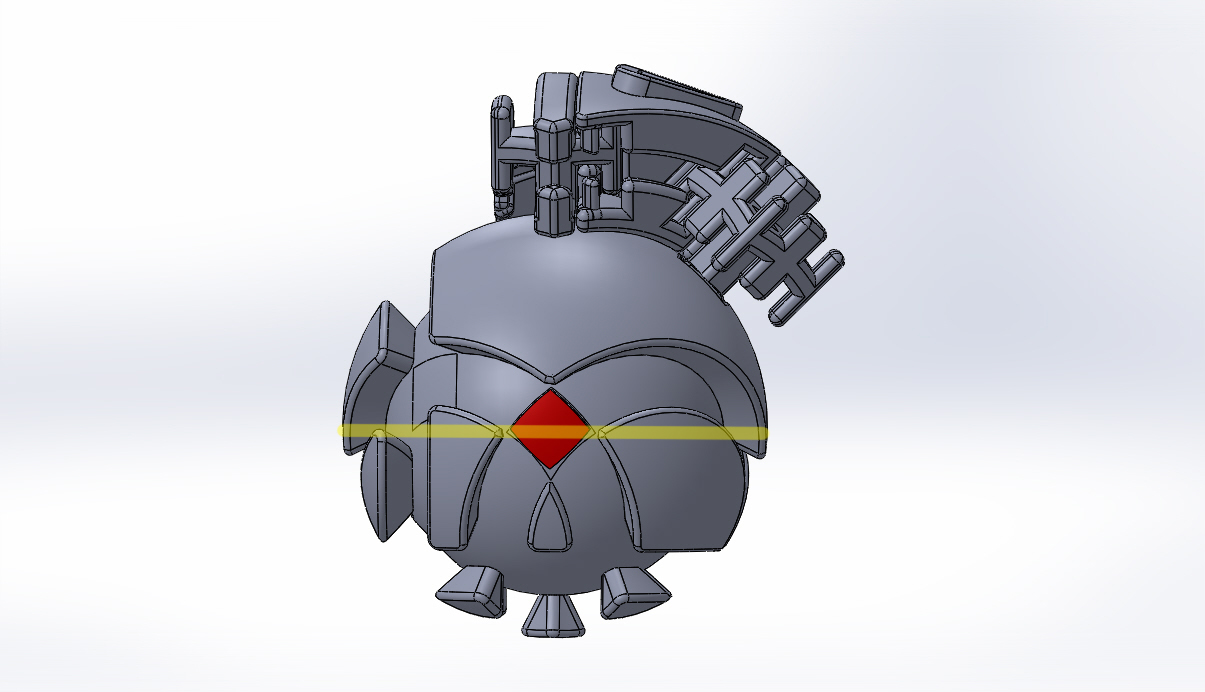
Version 4 – 2015
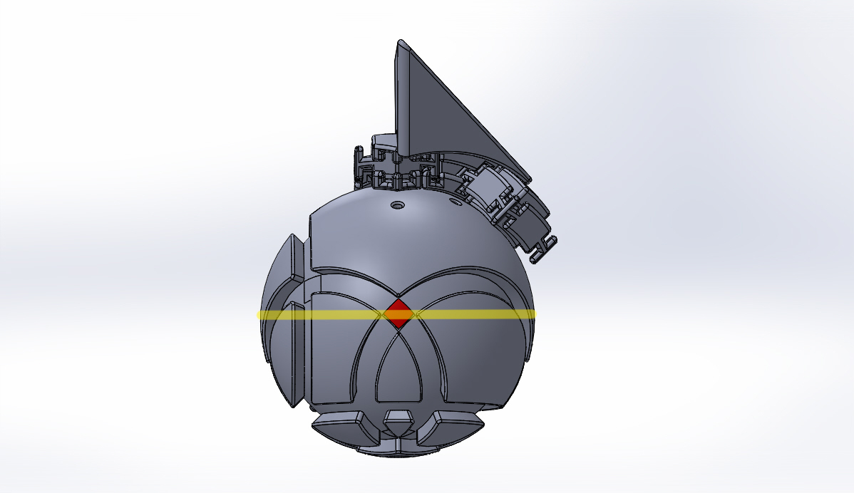
The new core sinks the brads for the center connections by about 1mm relative to all the other terminals.

I also fixed a few other small issues at the same time.
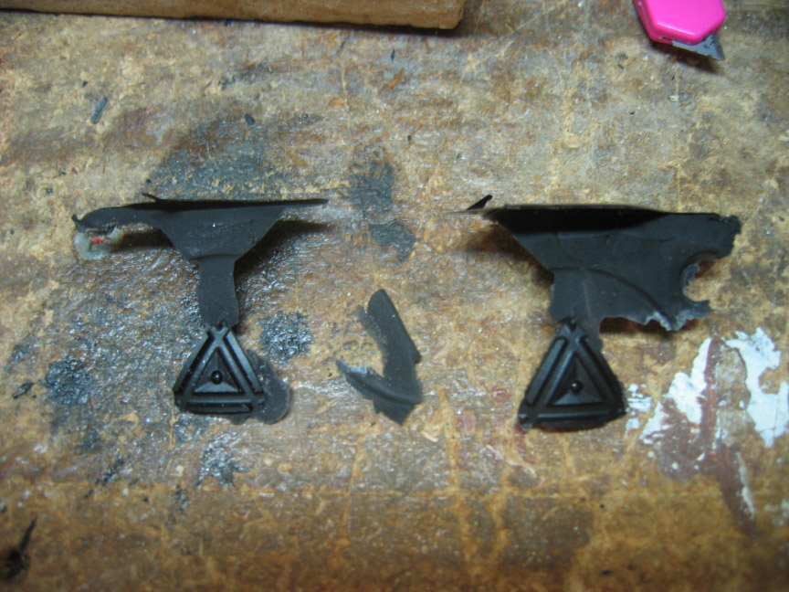
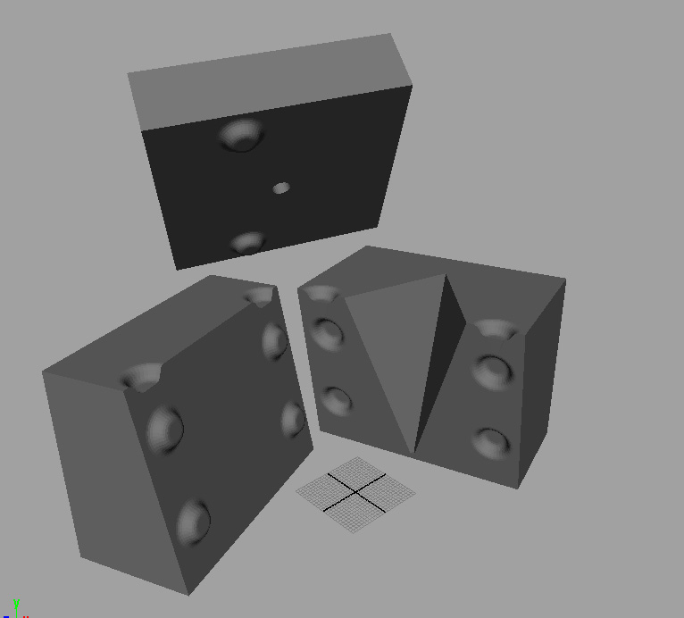
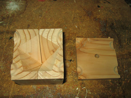
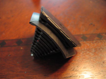
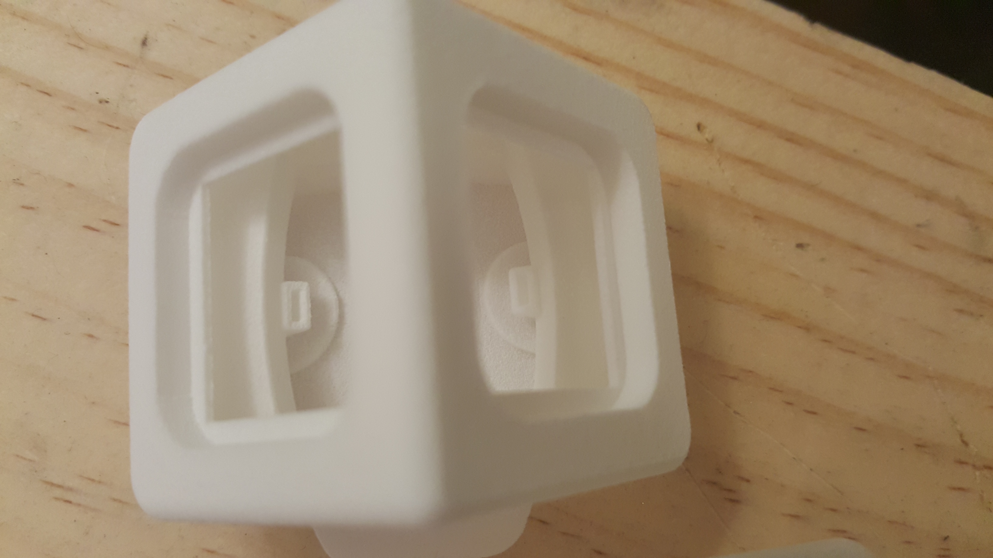
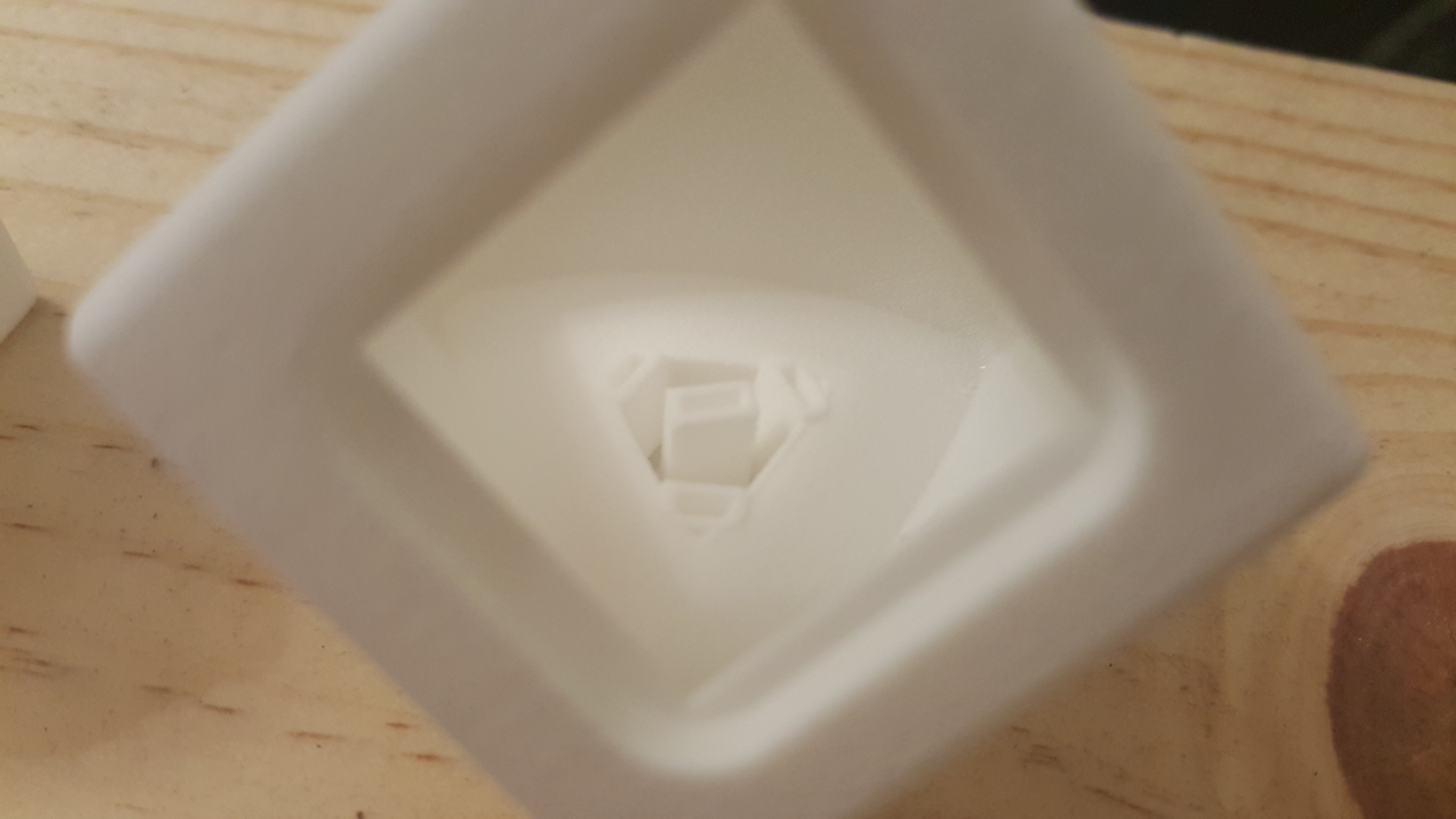
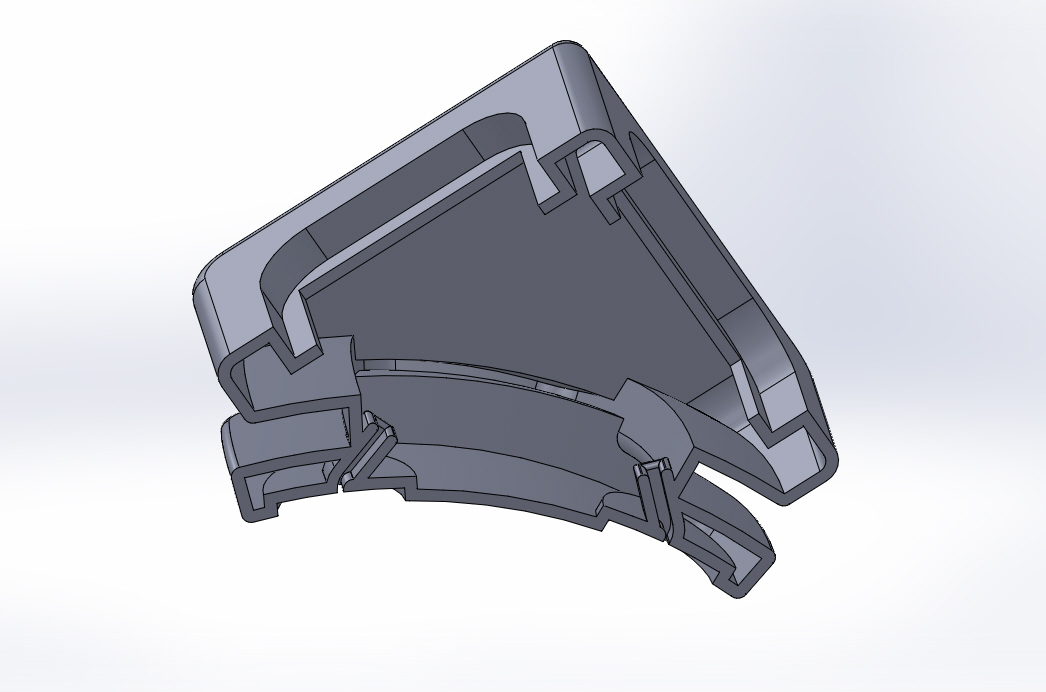
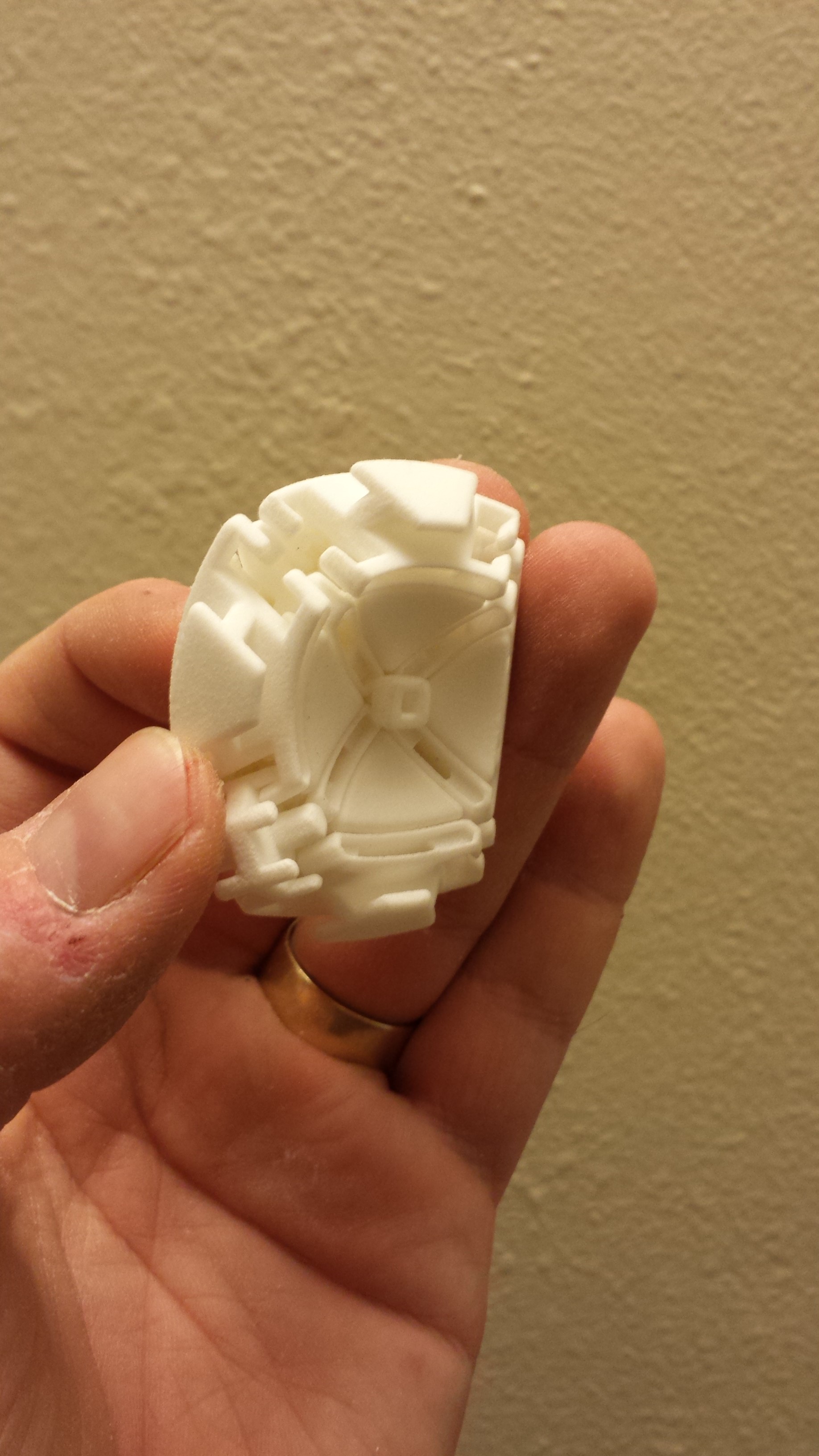
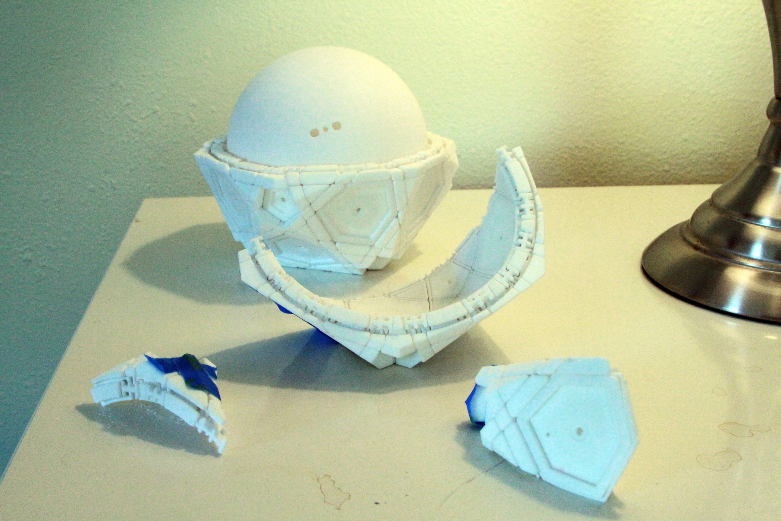
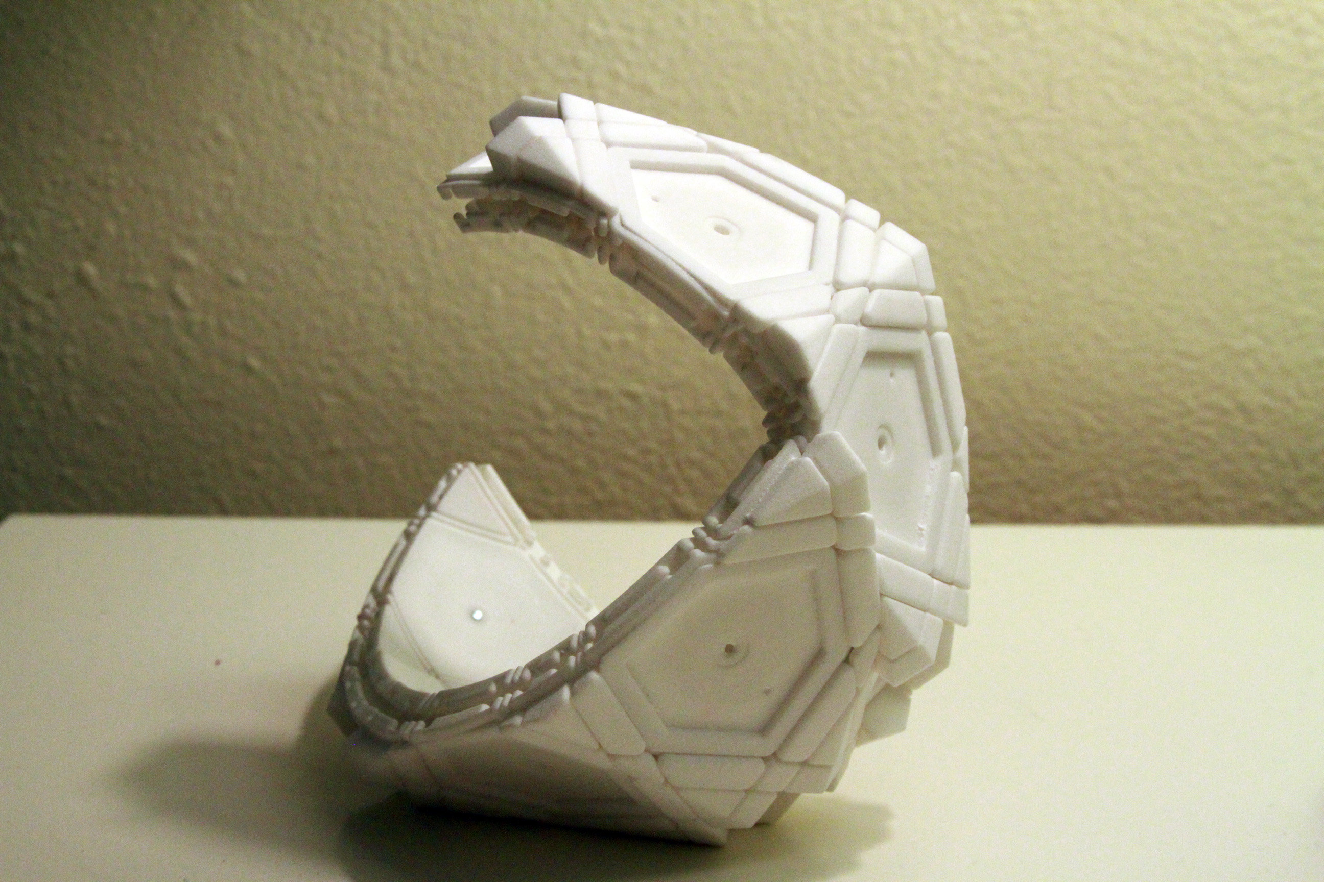
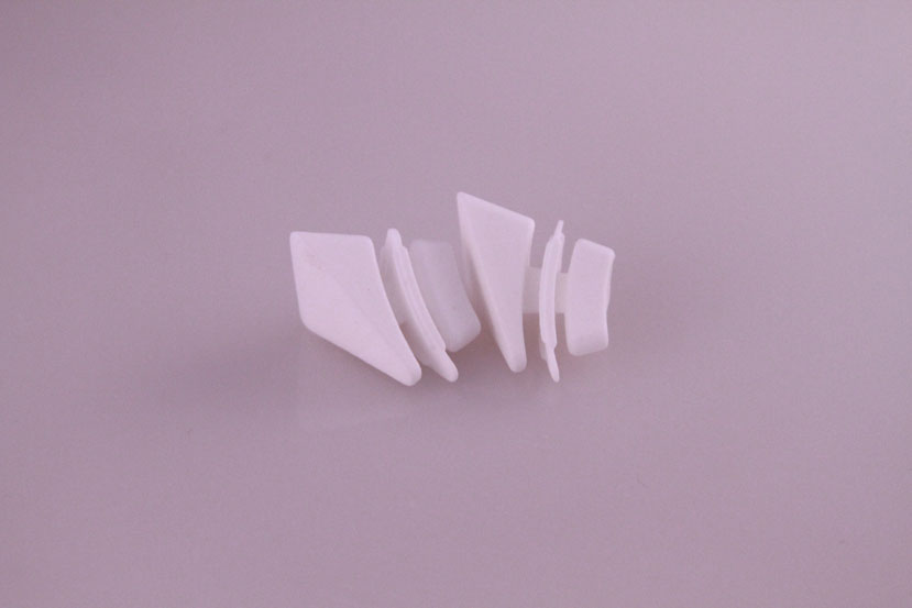
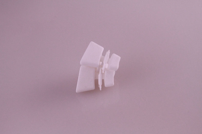
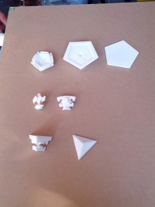
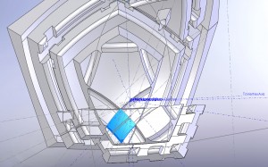
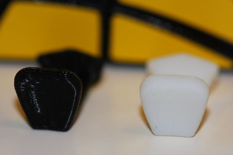
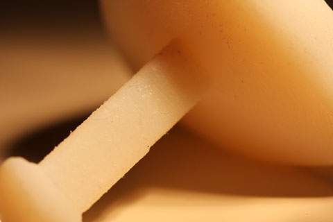
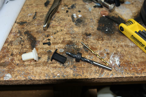
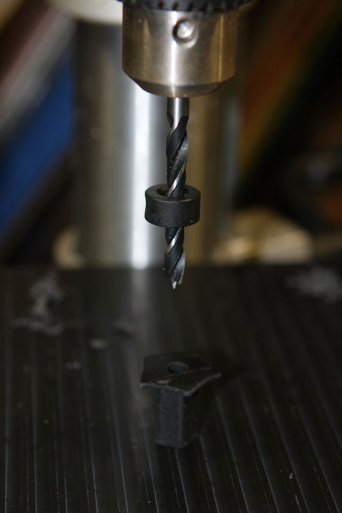
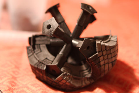
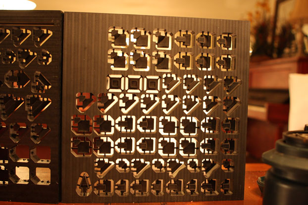
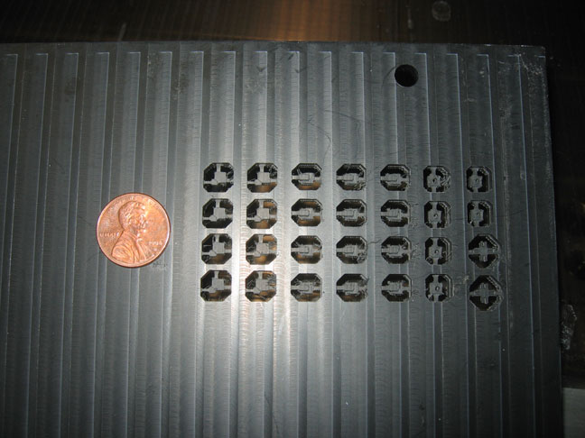
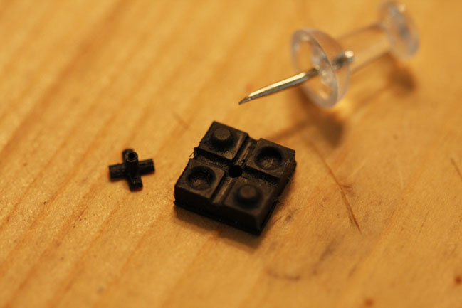
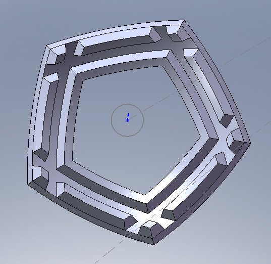
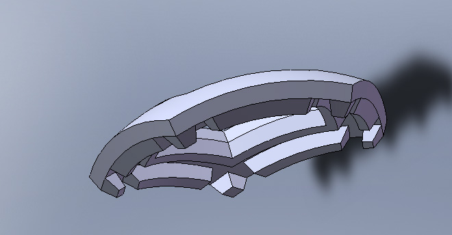
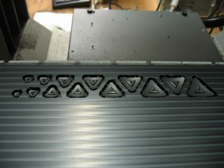
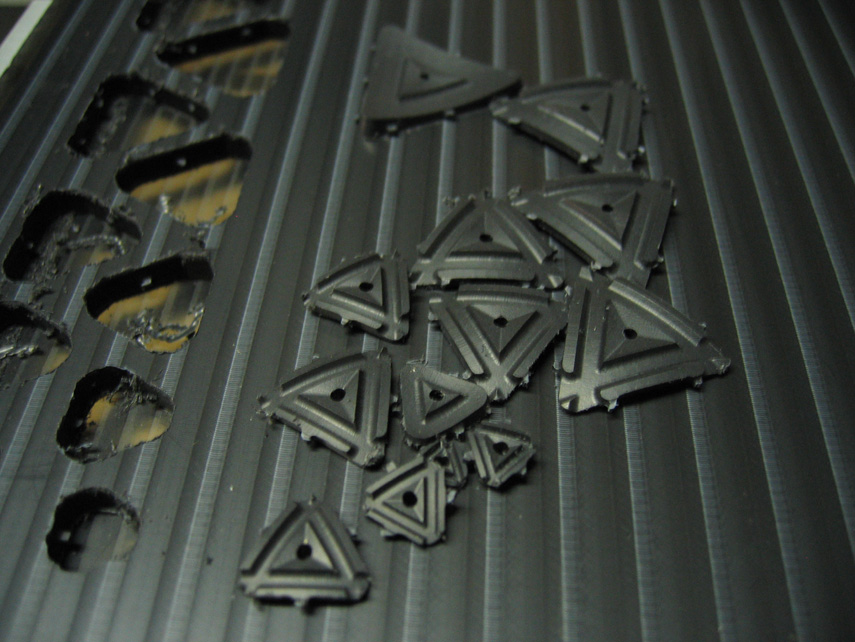
The new corners were broken into two pieces so that the brads could be inserted more easily.
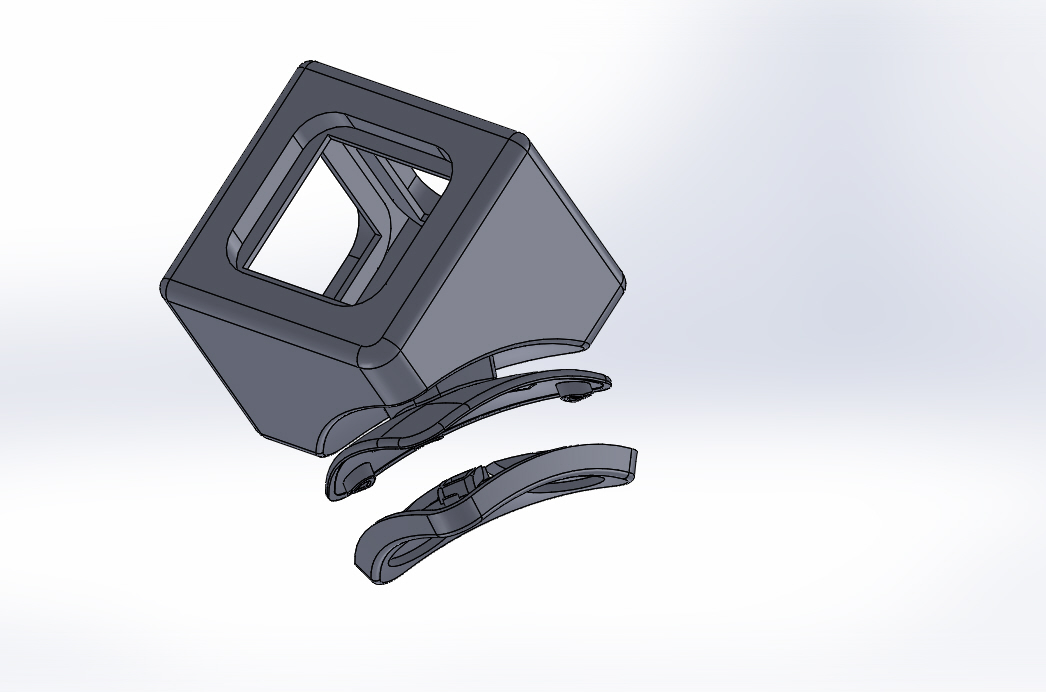
Here is a section view showing the tracks inside.
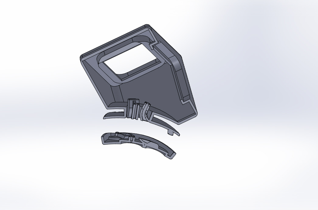
Brads could be inserted into them separately to clear out any clogged powder. Then, the brads could finally be inserted into the bottom part, and then threaded into the top part, before simply pressing the two together.
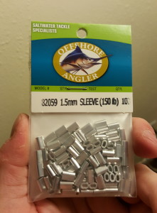
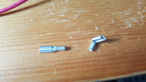
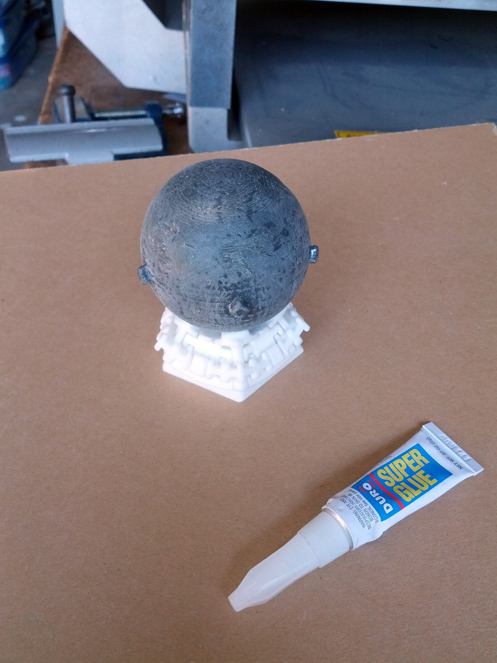
Soldering was a major time sink in past iterations, so I tried using fishing line crimps to connect wires. These saltwater line crimps are the perfect size to slide over the tail of a brad.
In the end, I still had to solder, but at least the mechanical connection was much faster.
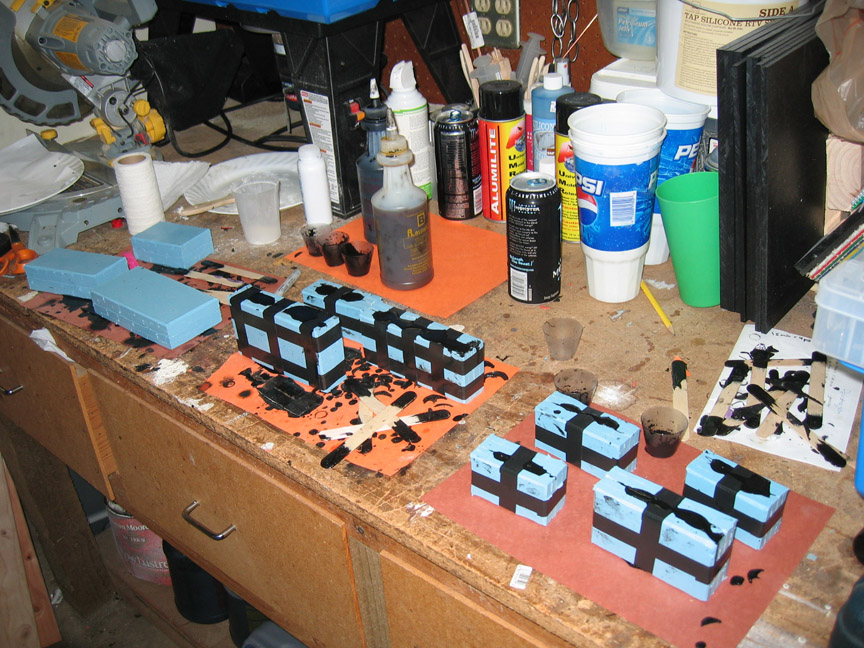
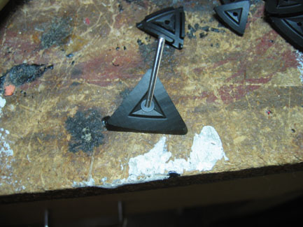
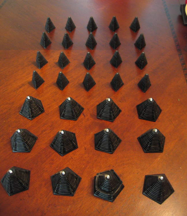
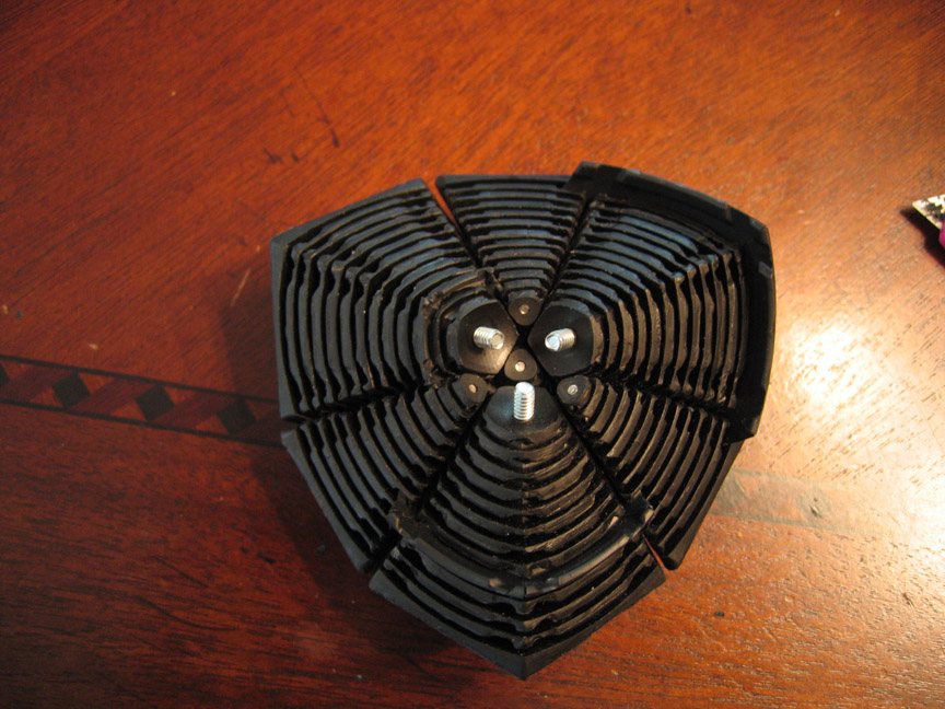
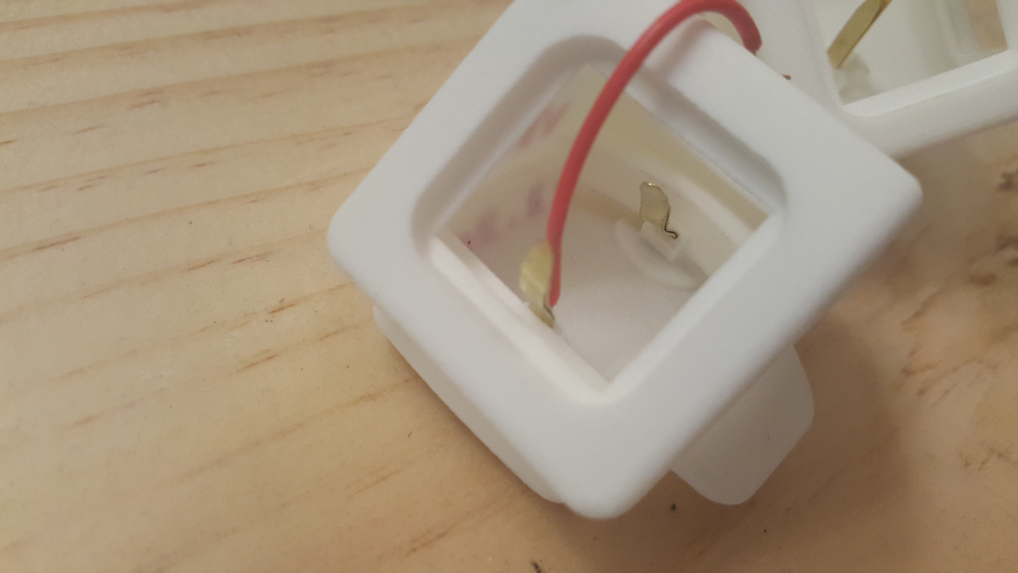
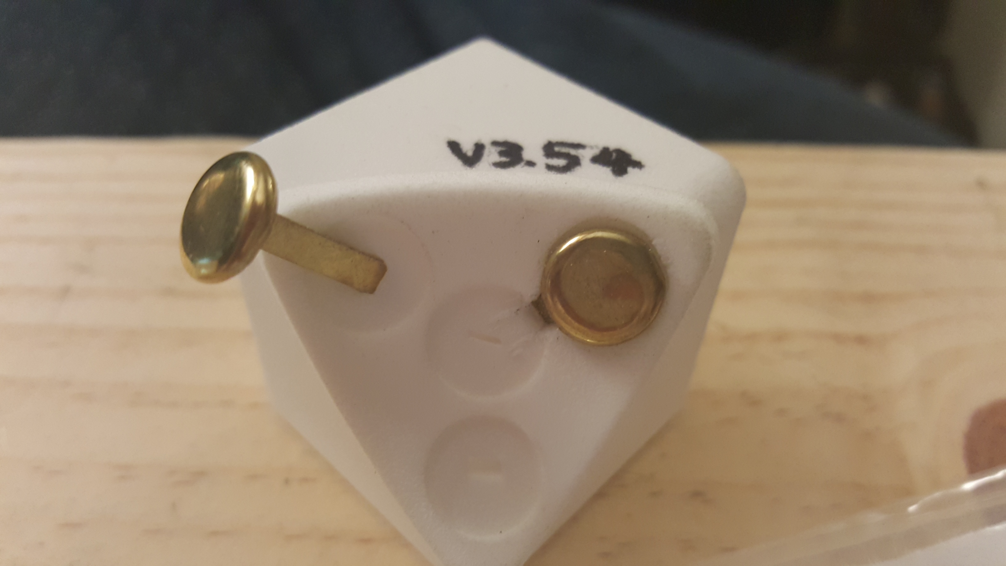
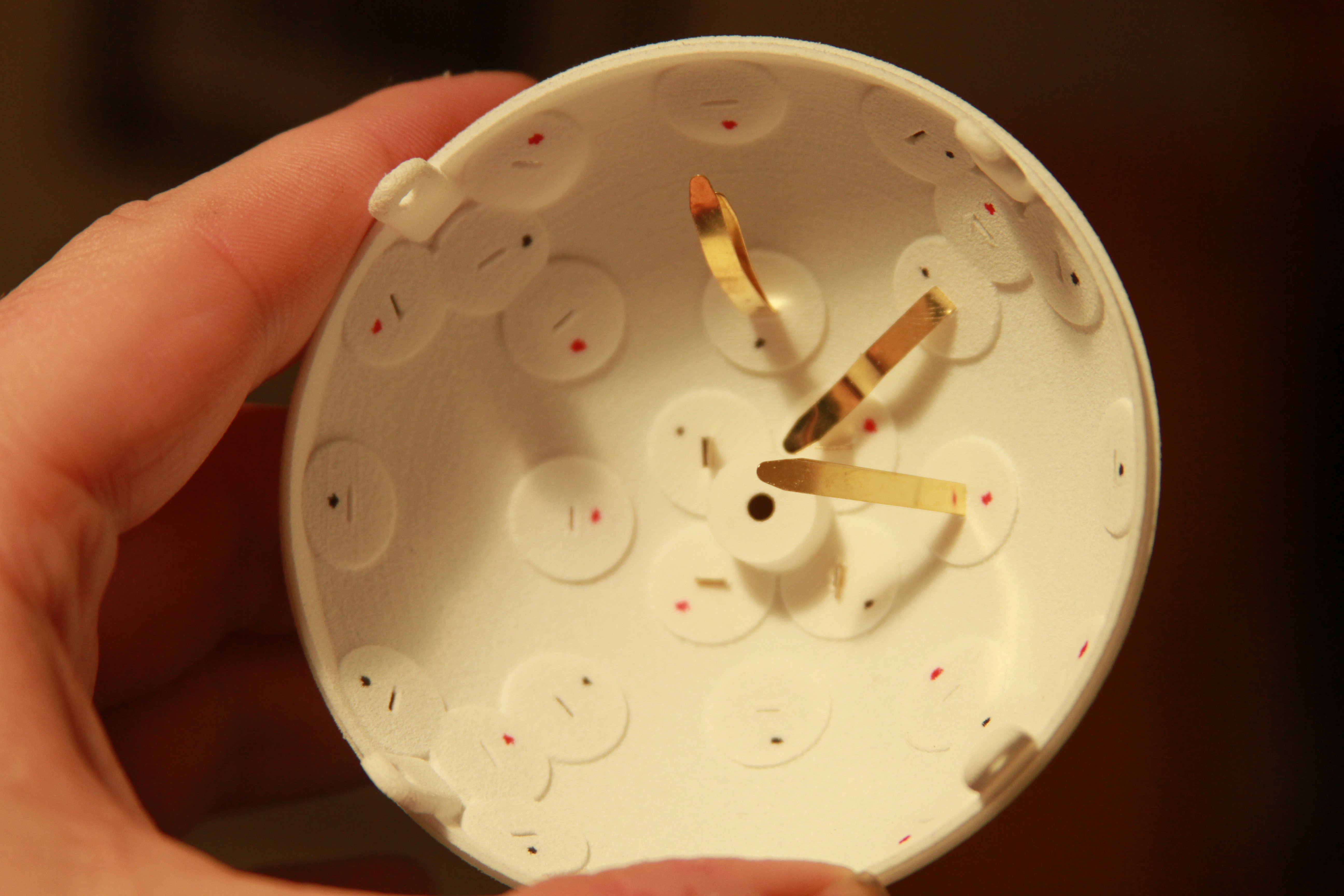
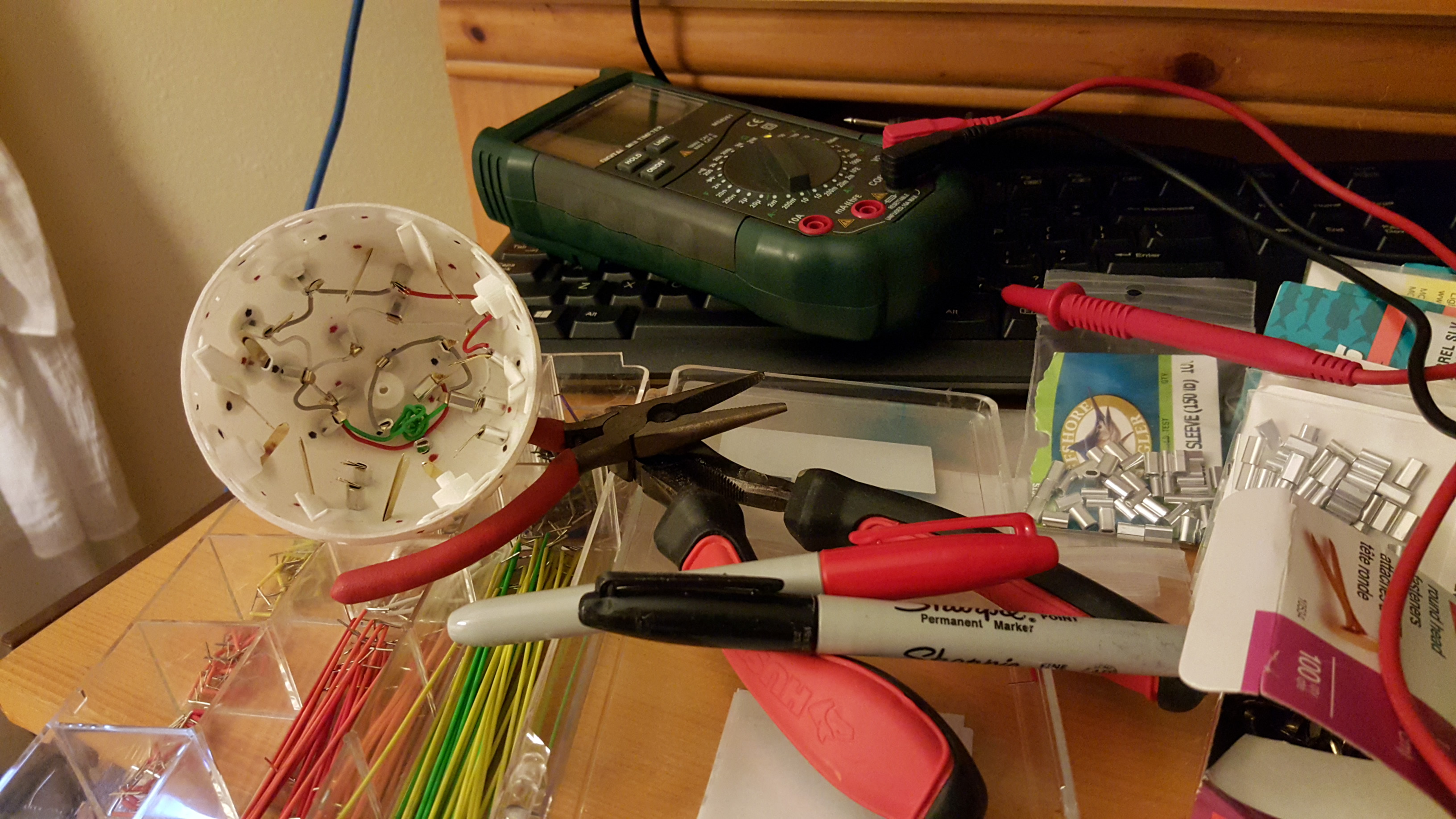
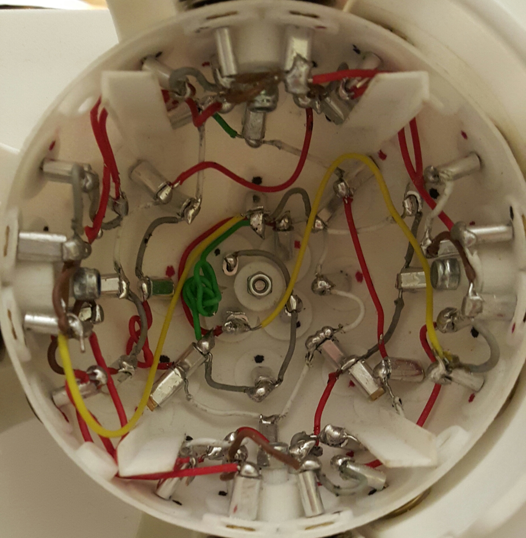
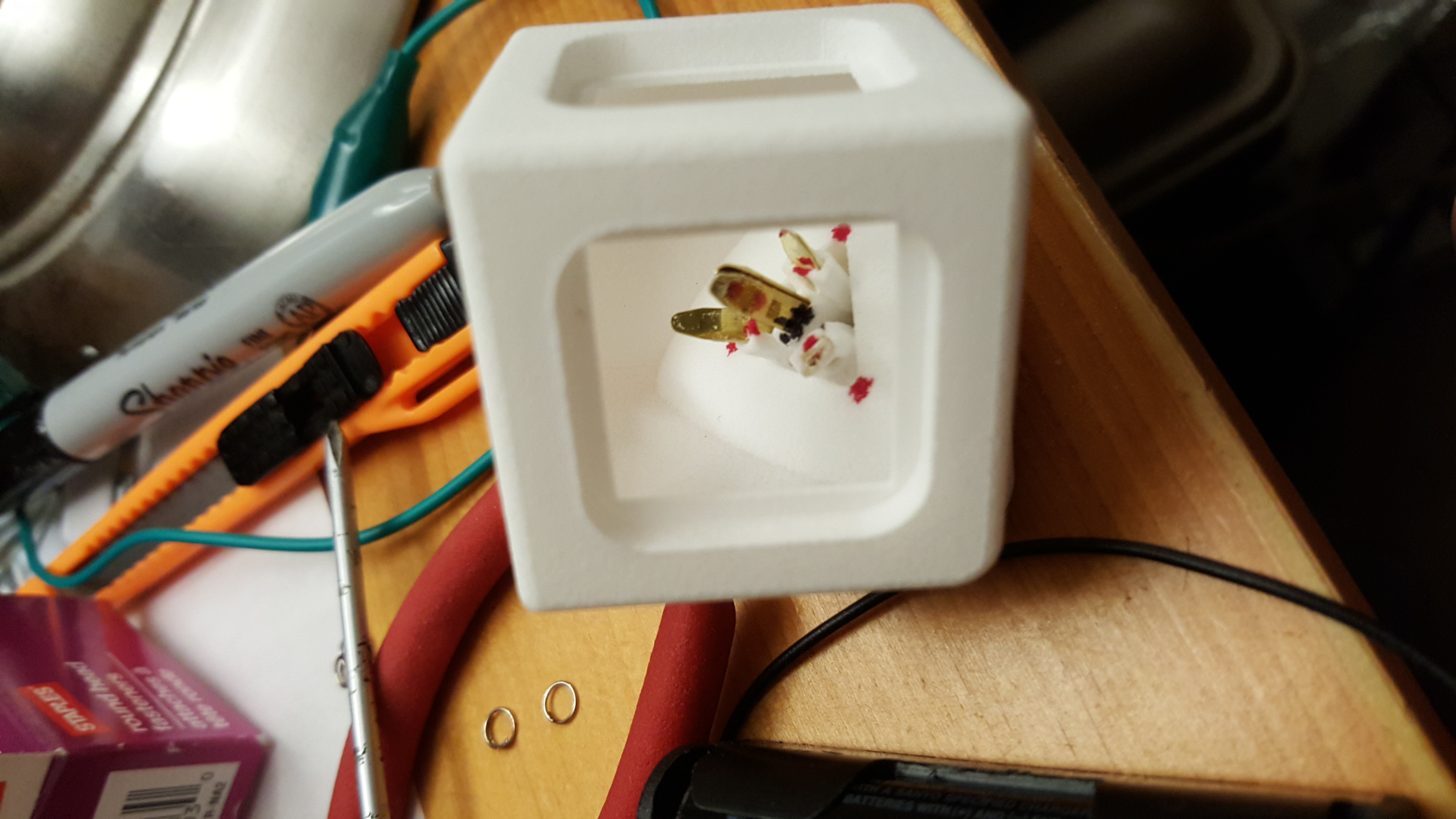
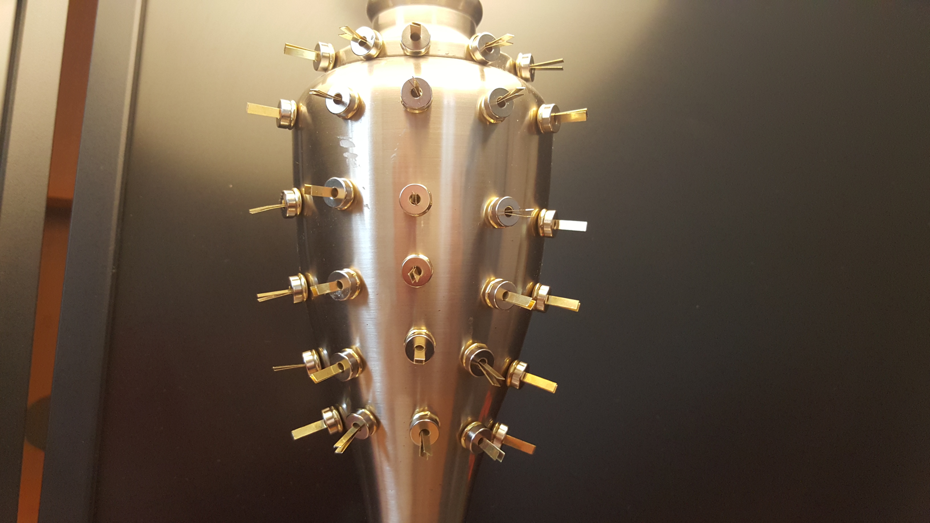
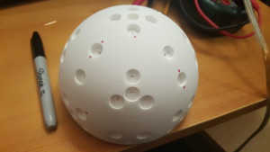
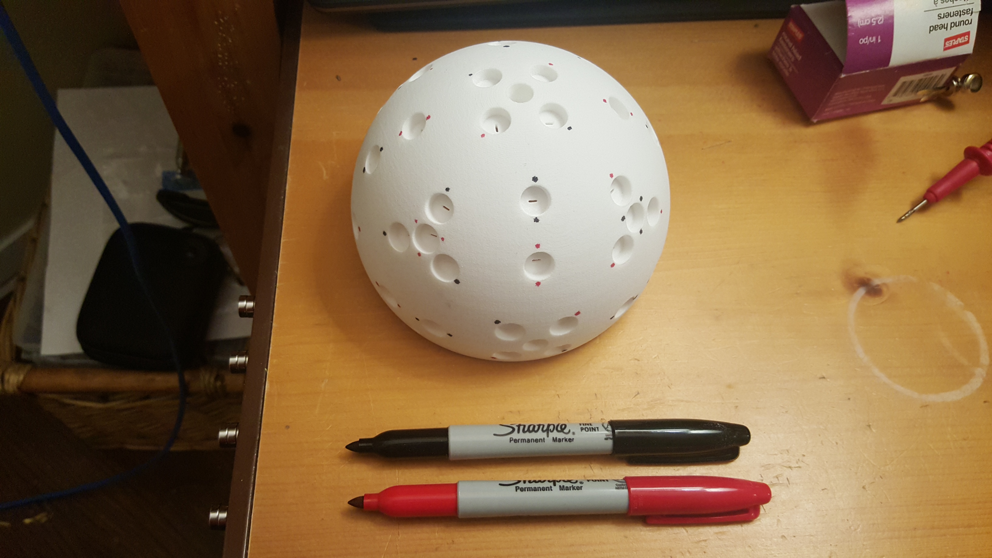
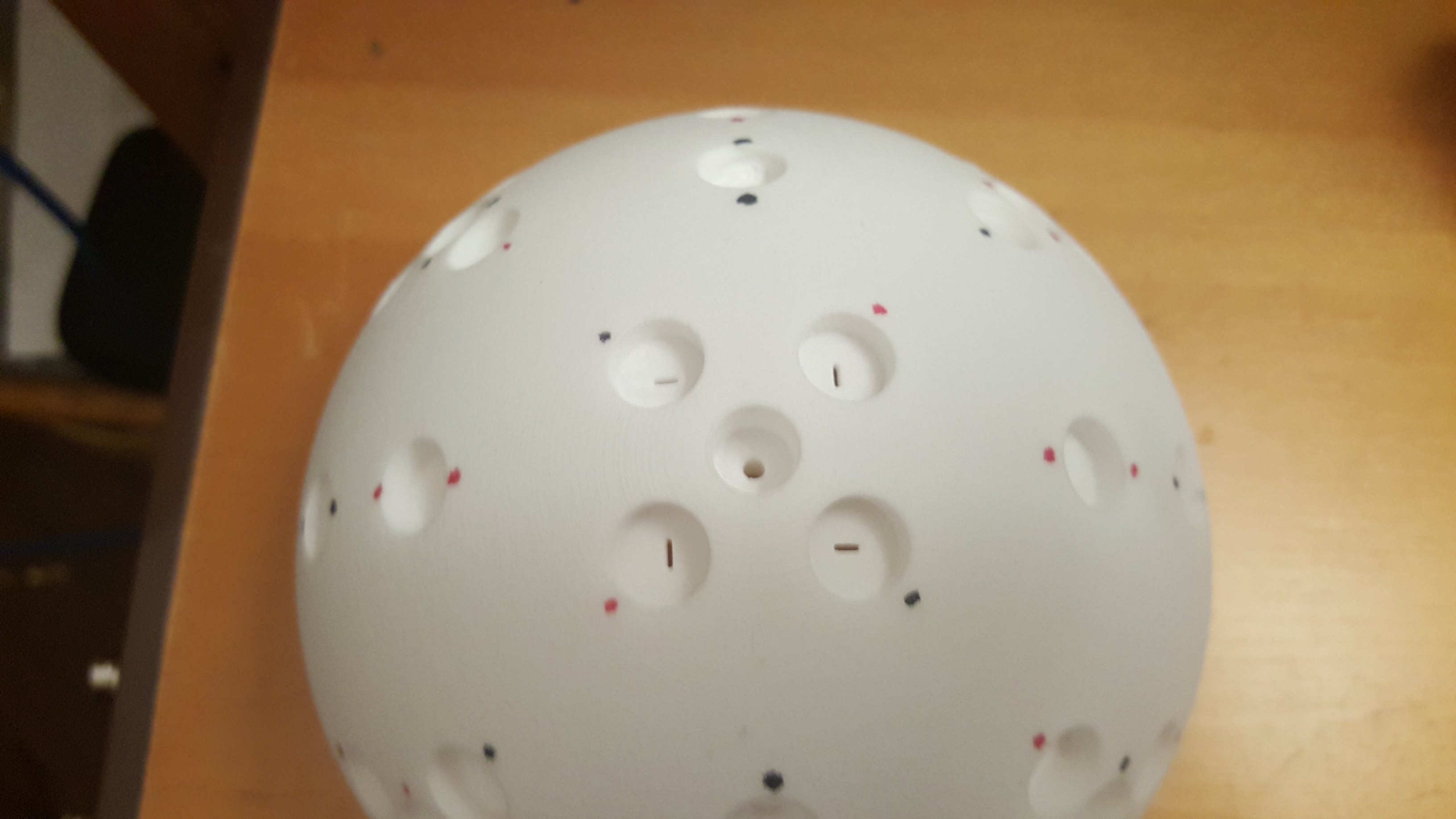
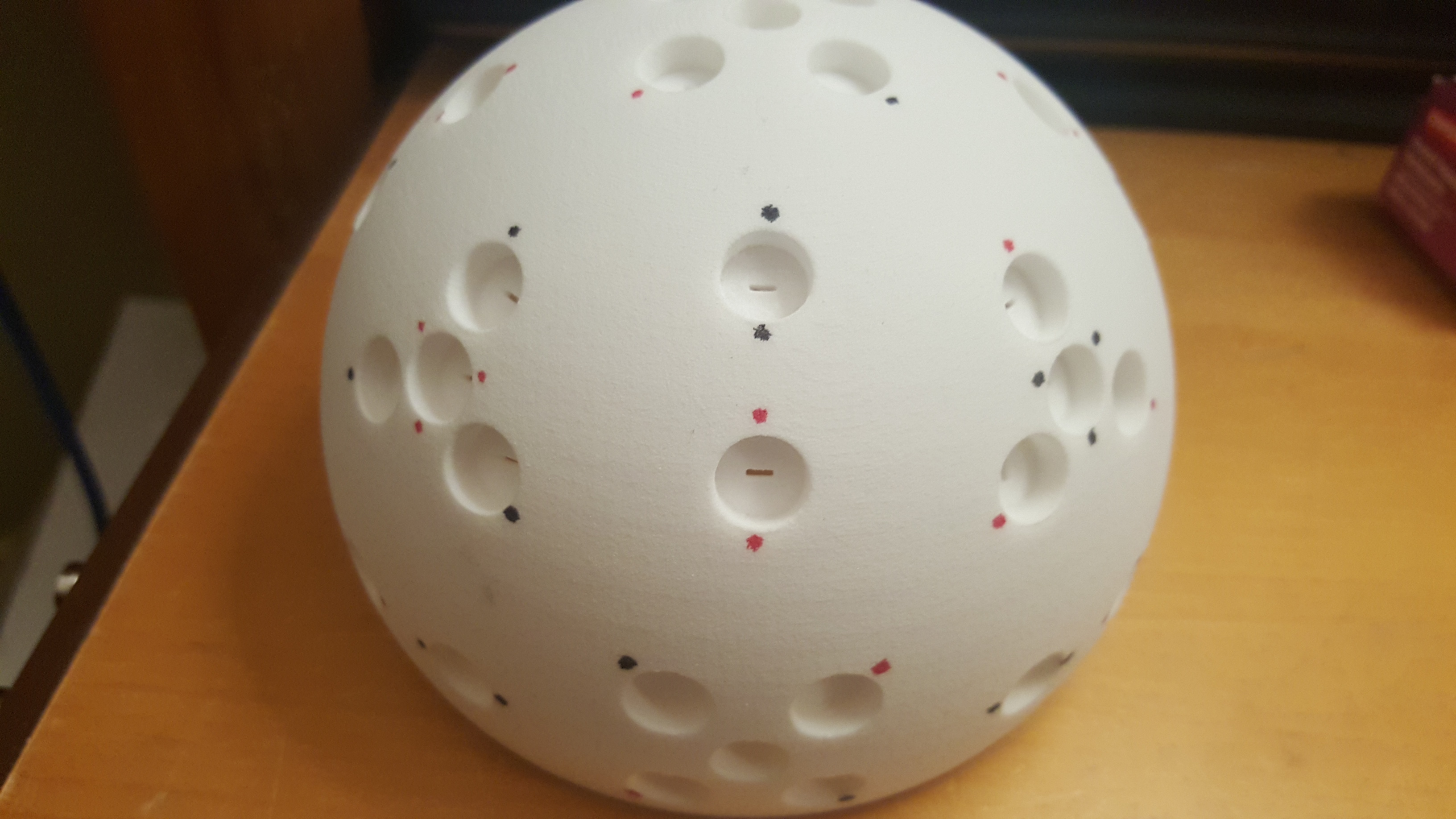
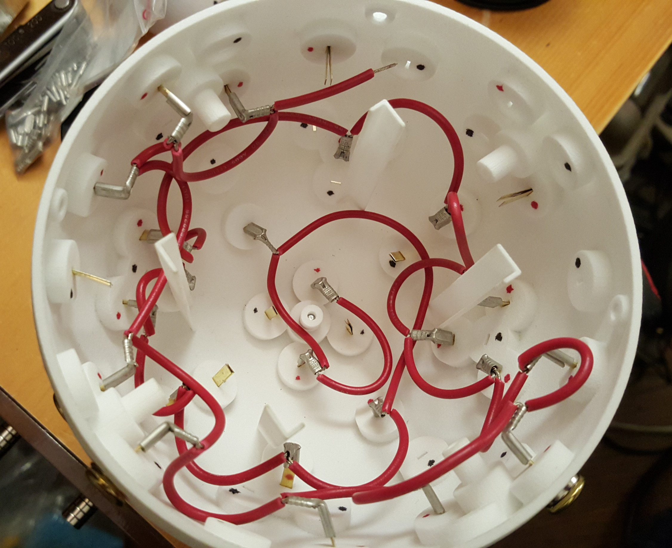
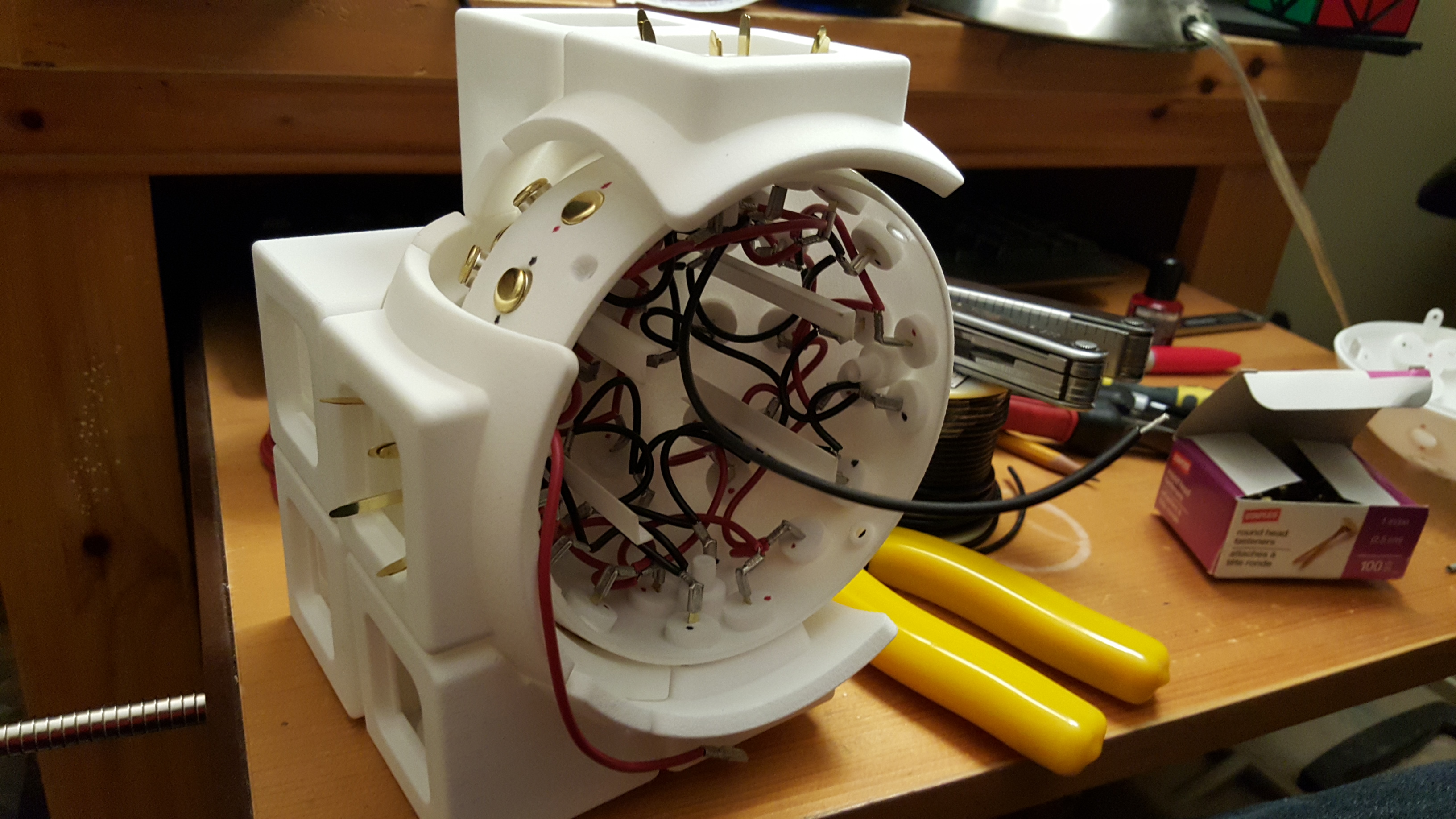
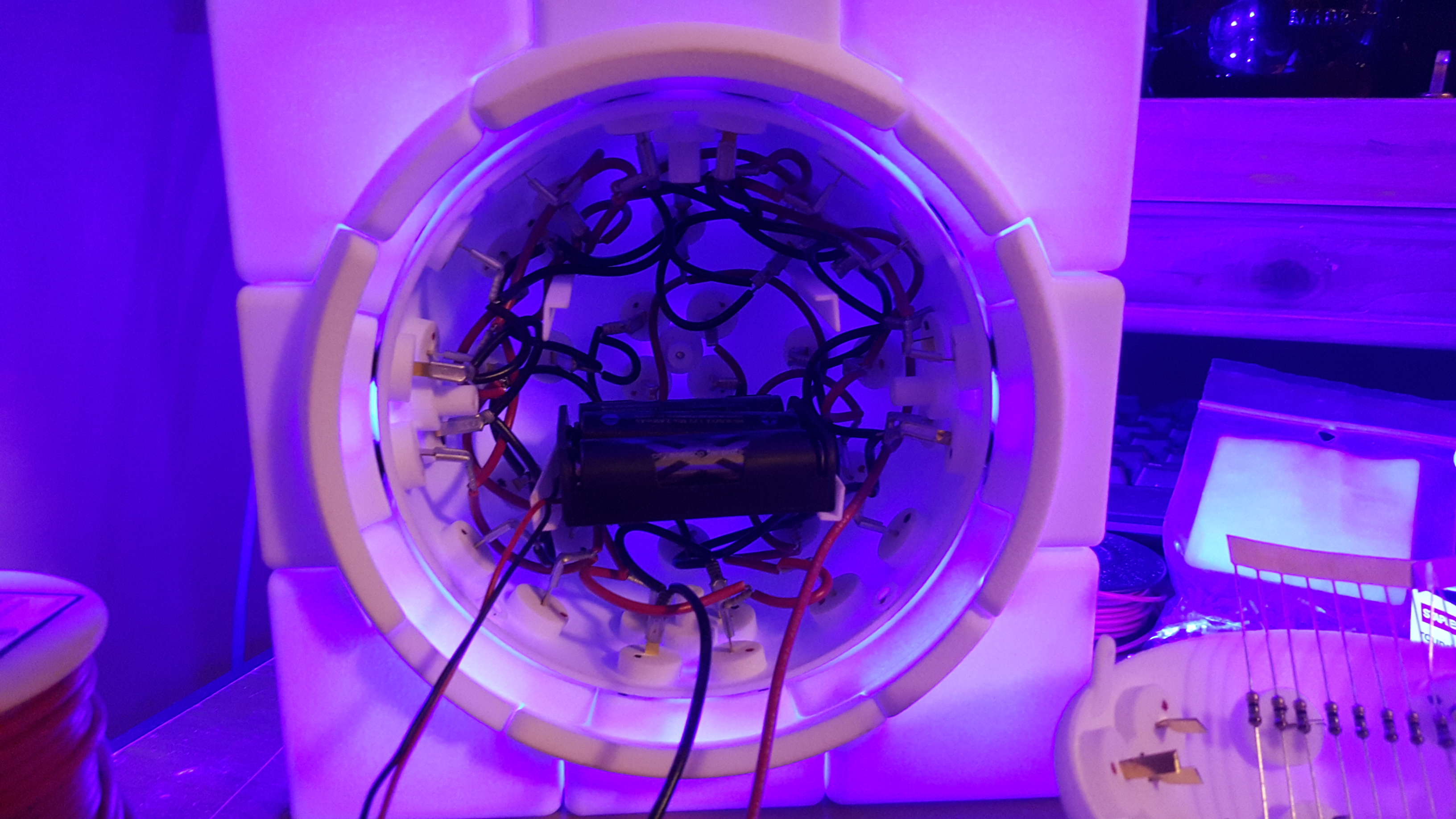
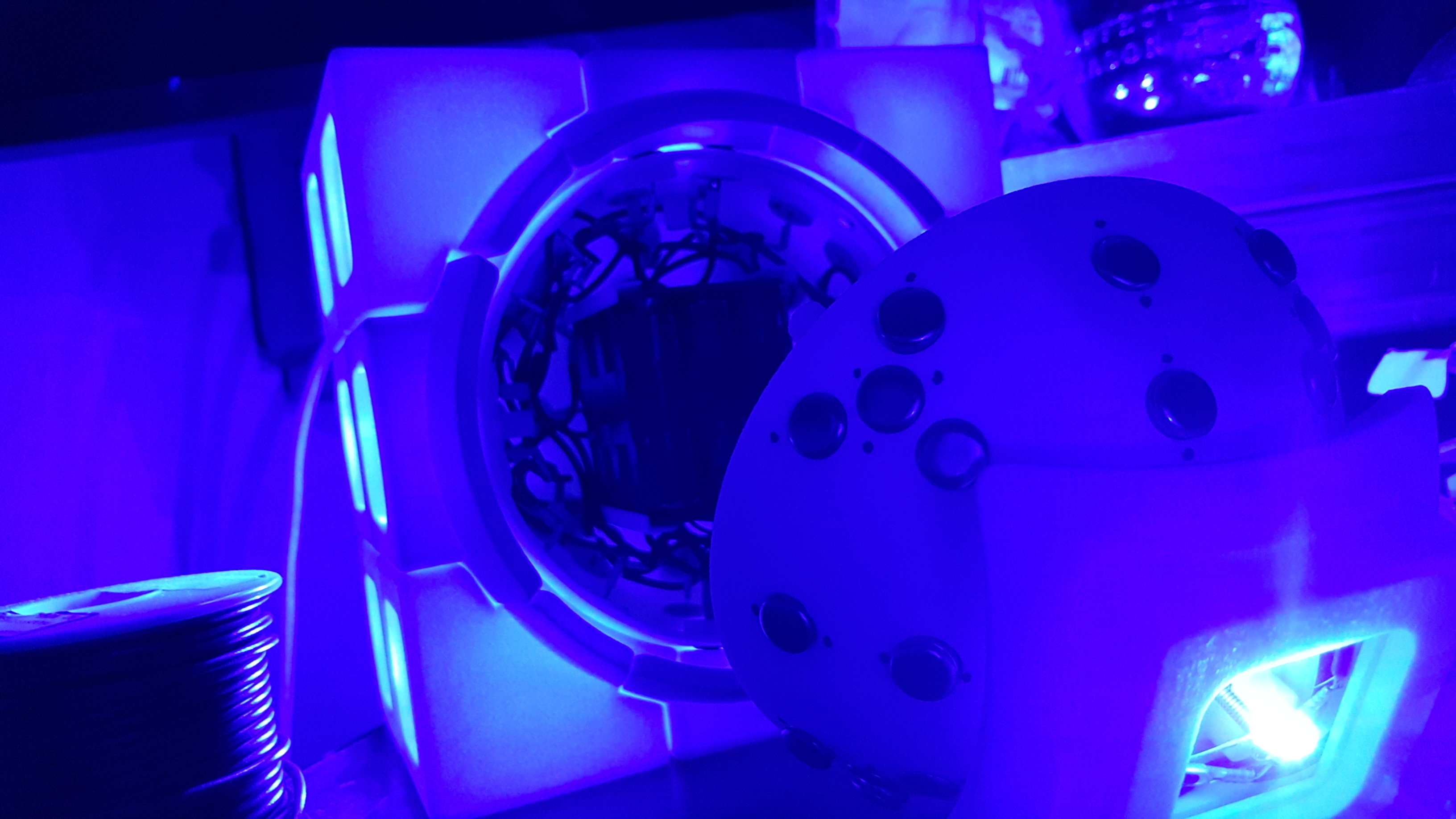
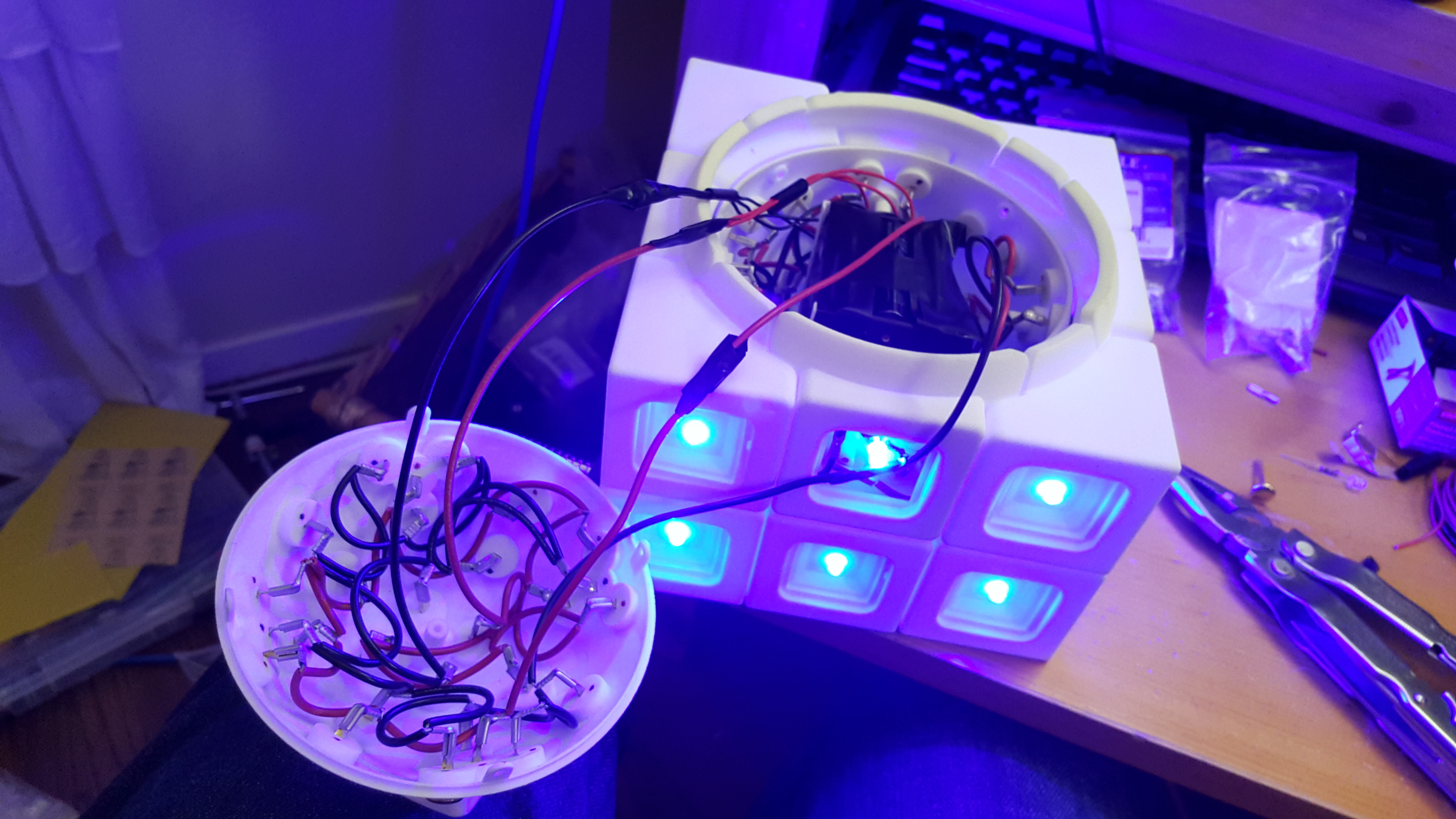
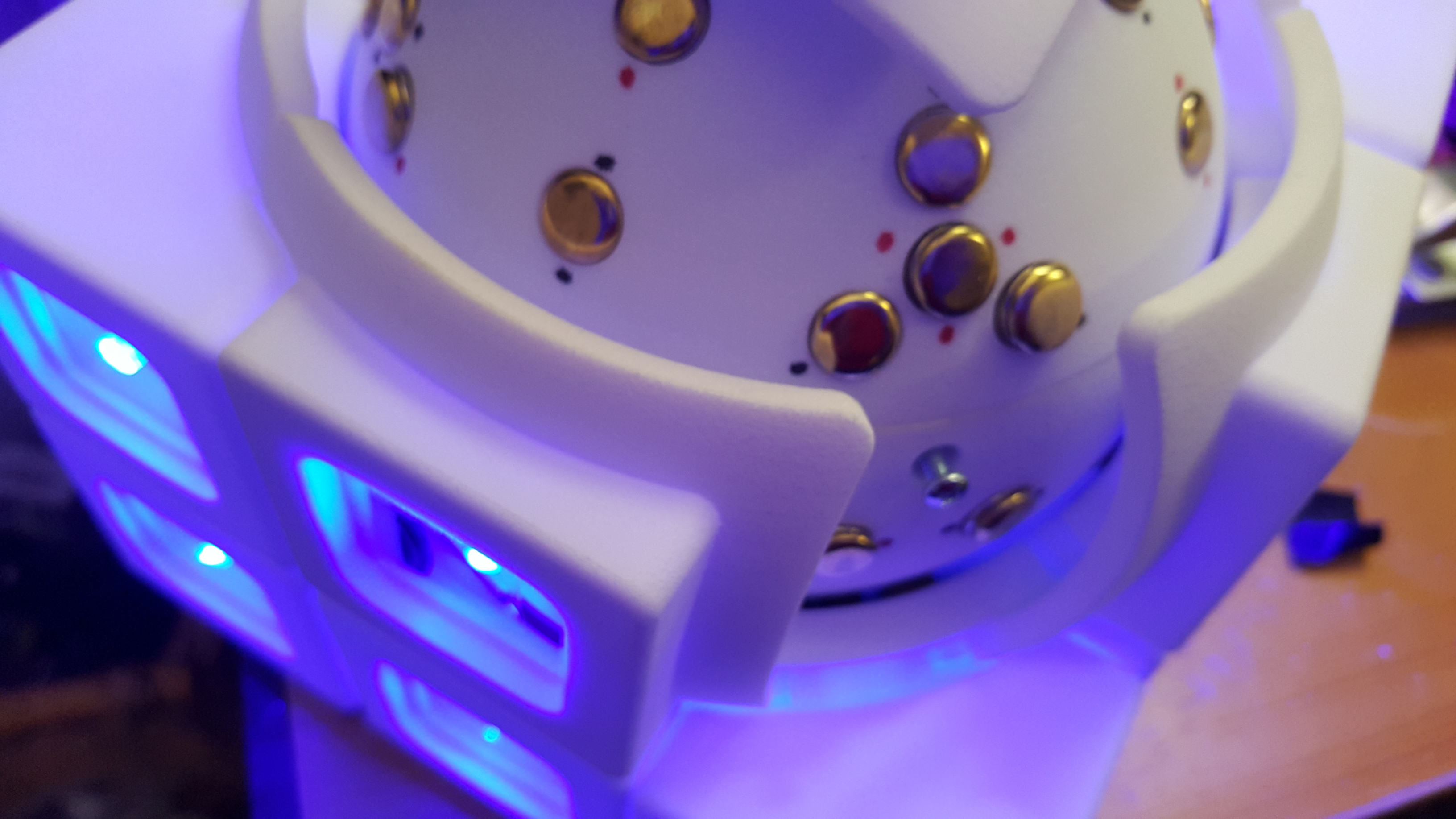
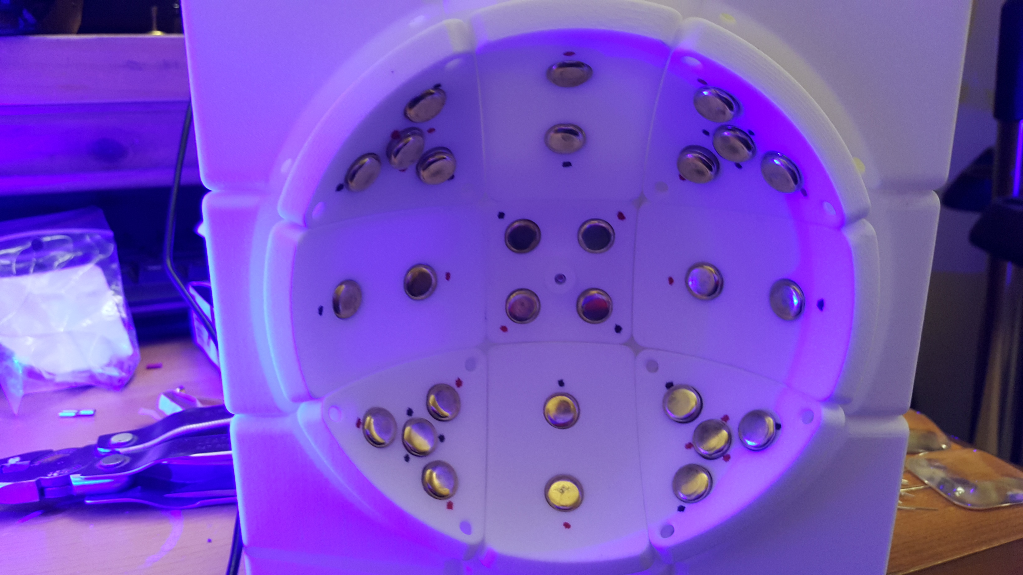
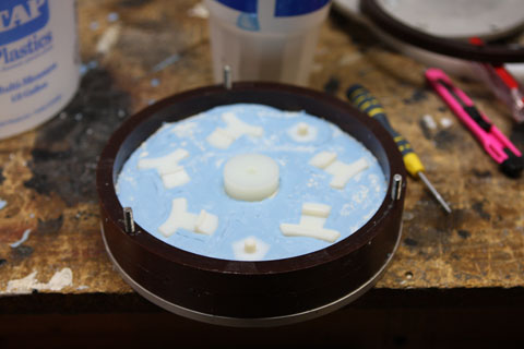
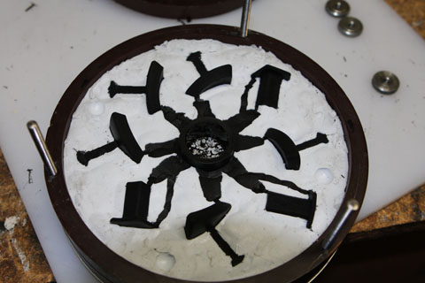
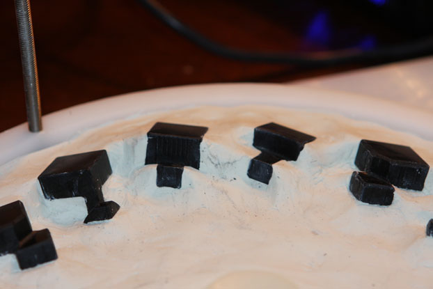
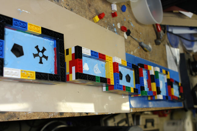
First, I mark the terminals on the core with black and red sharpie for negative and positive connections. Some brads are inserted:
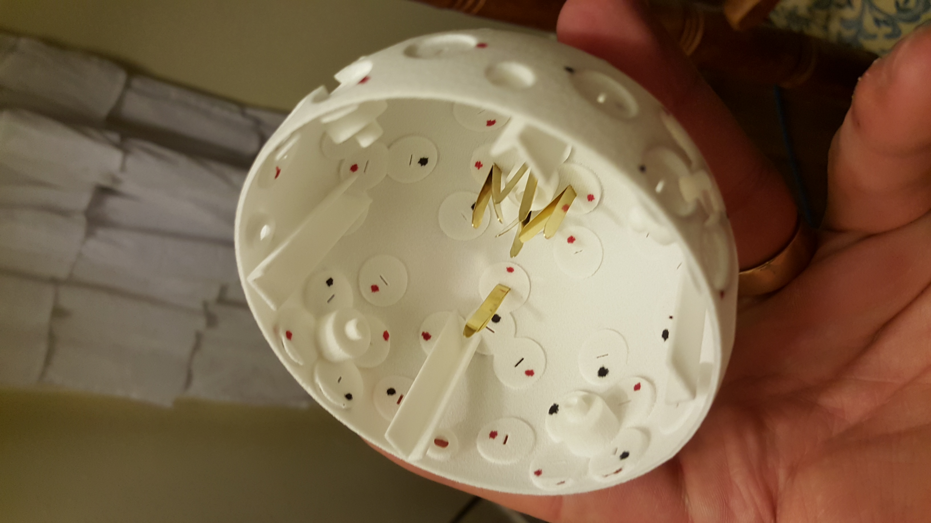
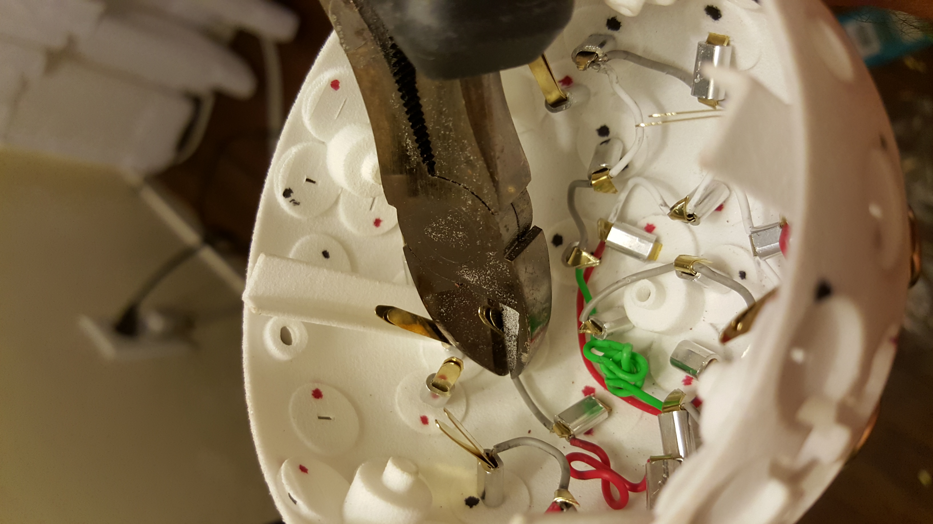
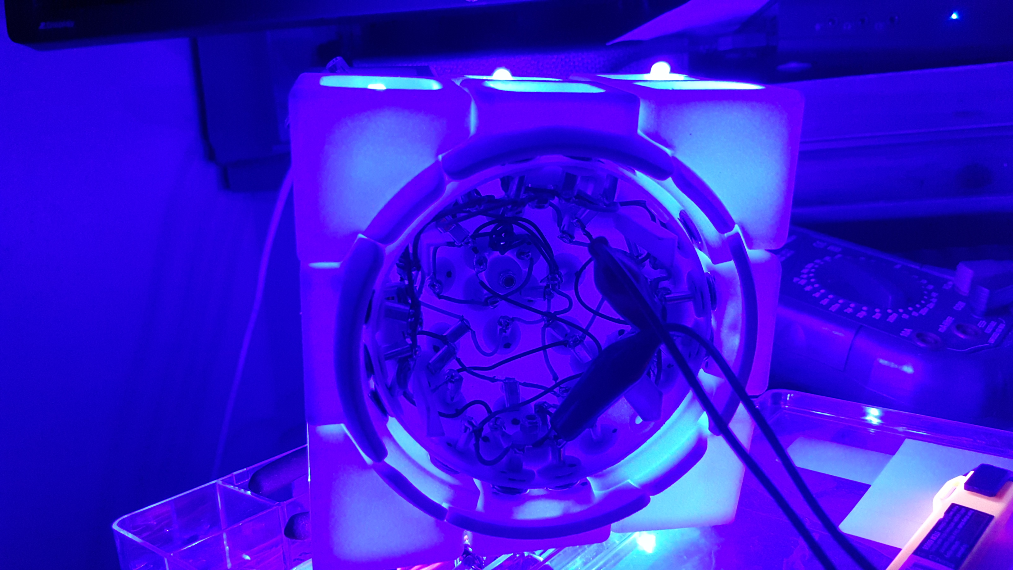
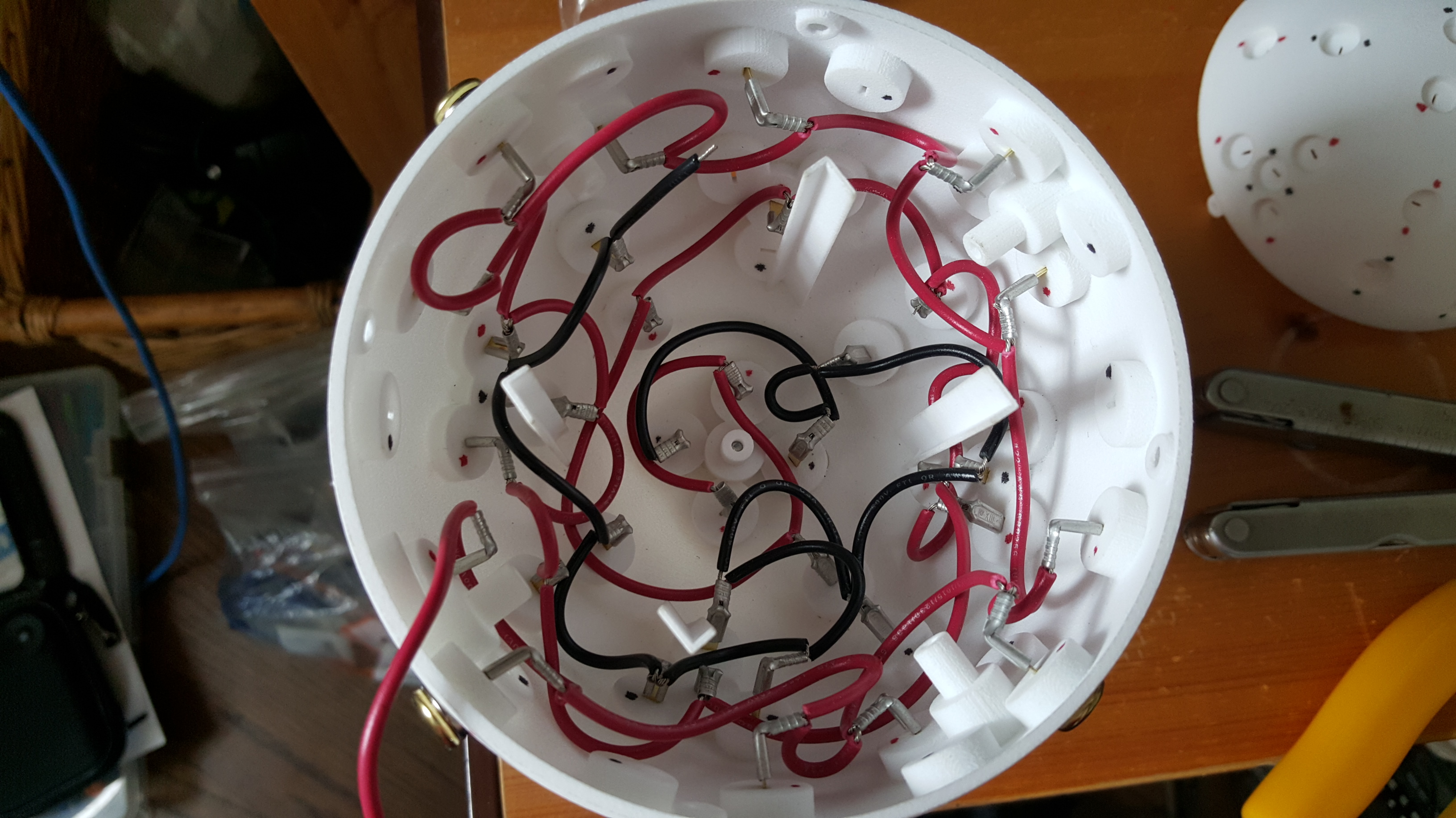
And then I begin connecting like polarity terminals with wire:

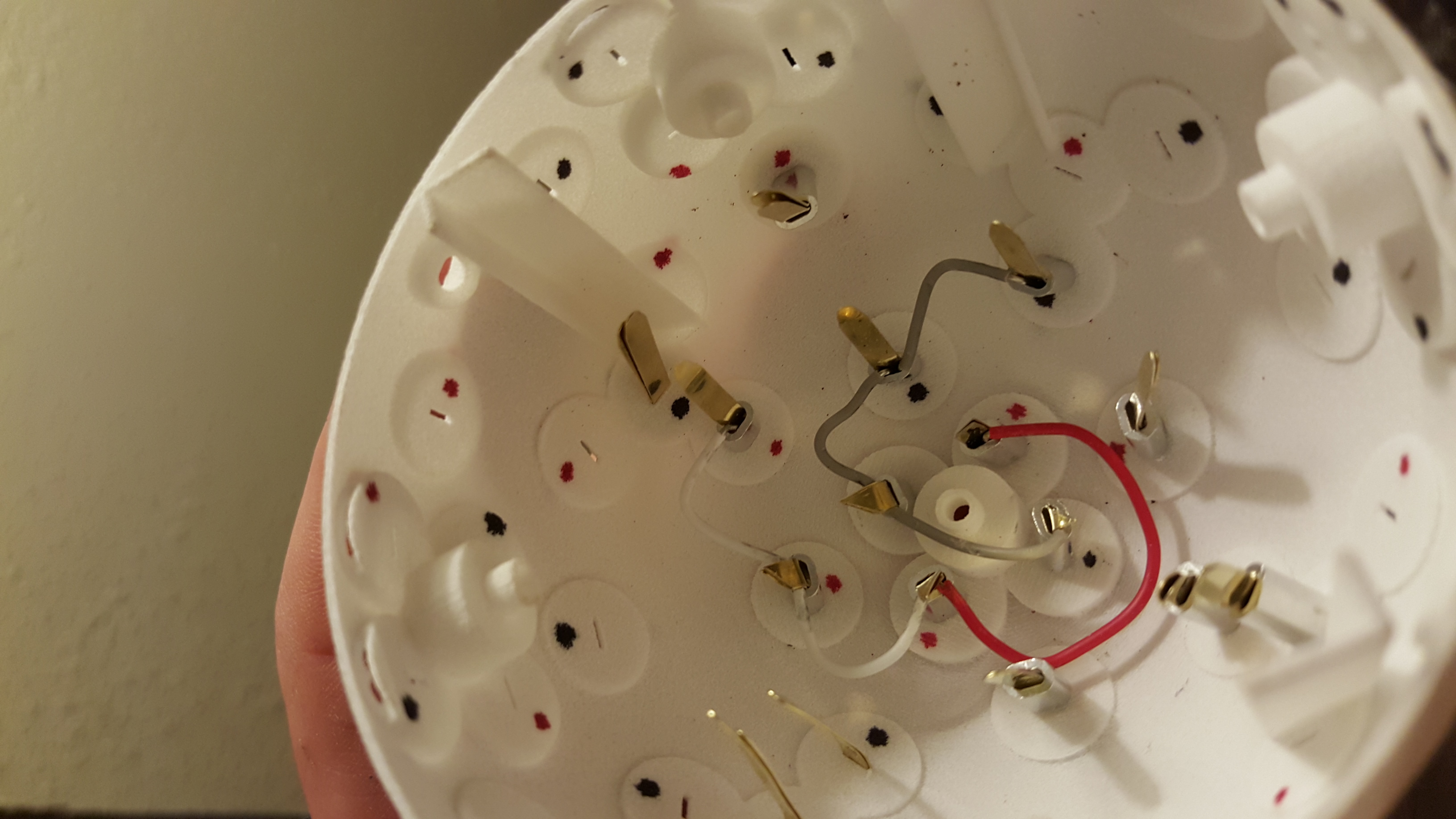
The wires spiral around from the center, going through all like polarity terminals.
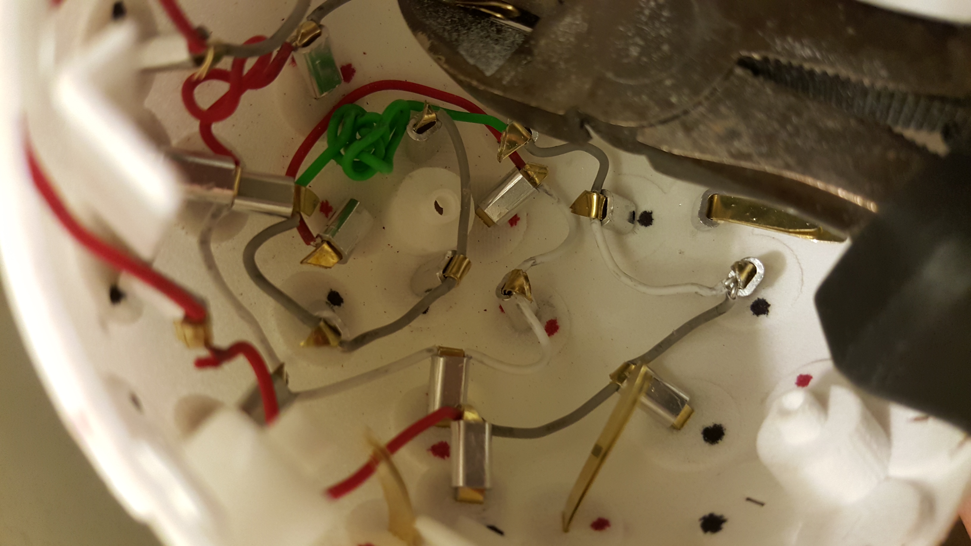

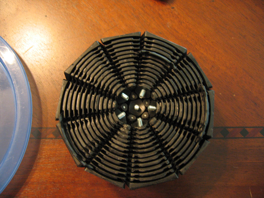
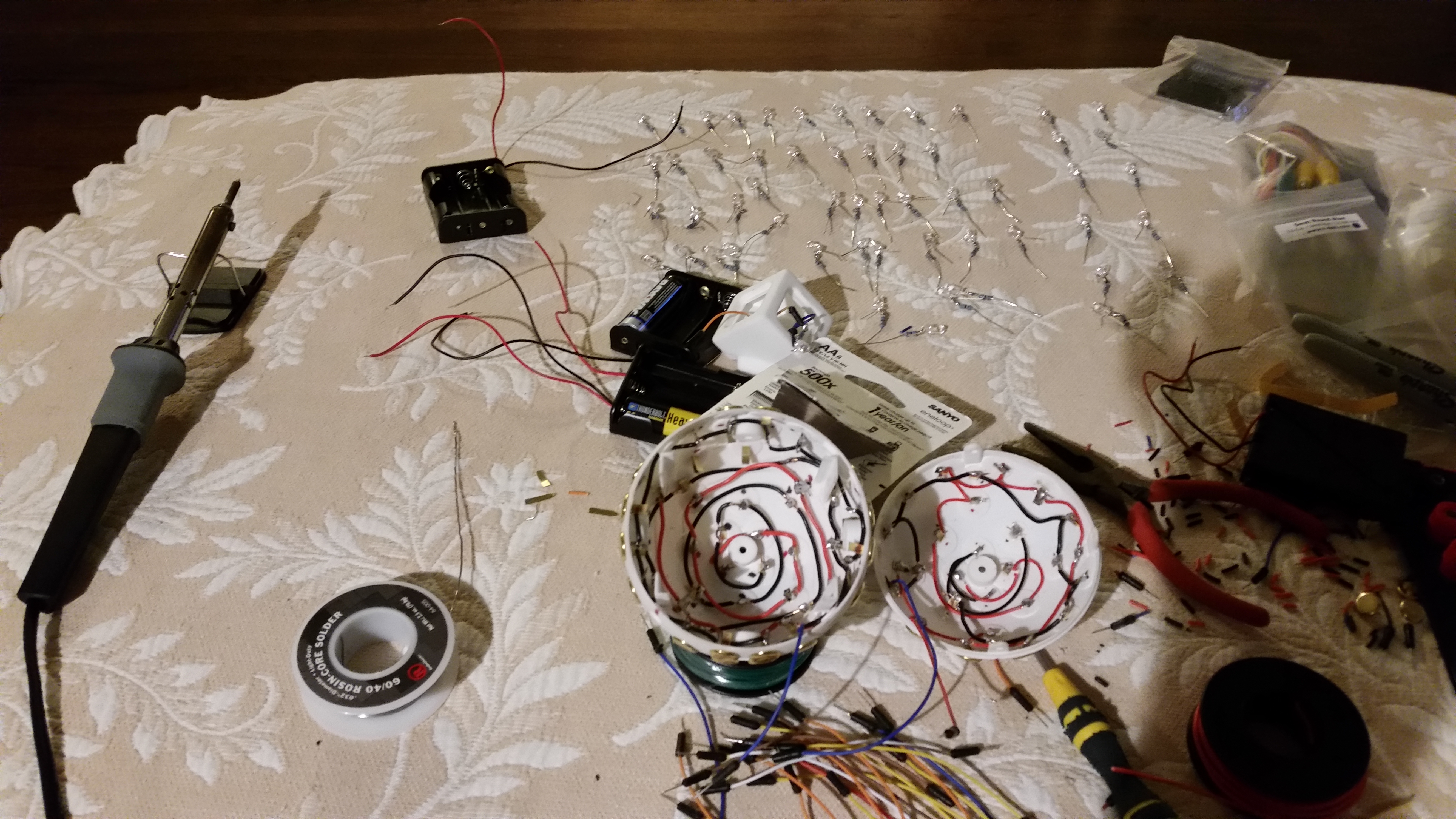
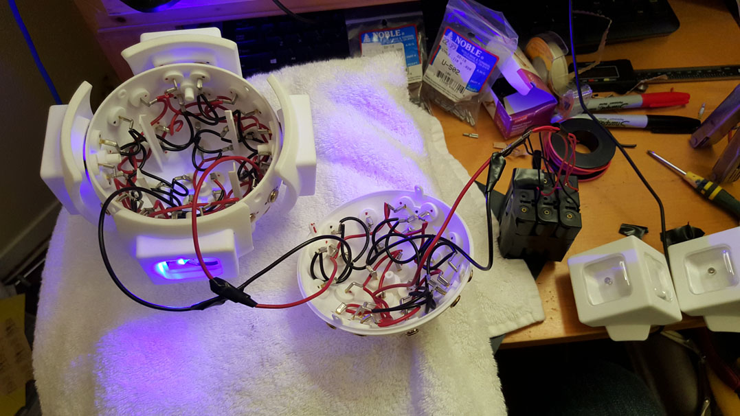
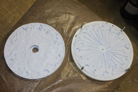
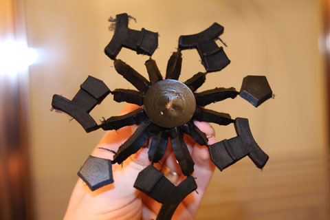
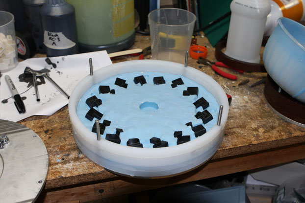
Almost done:
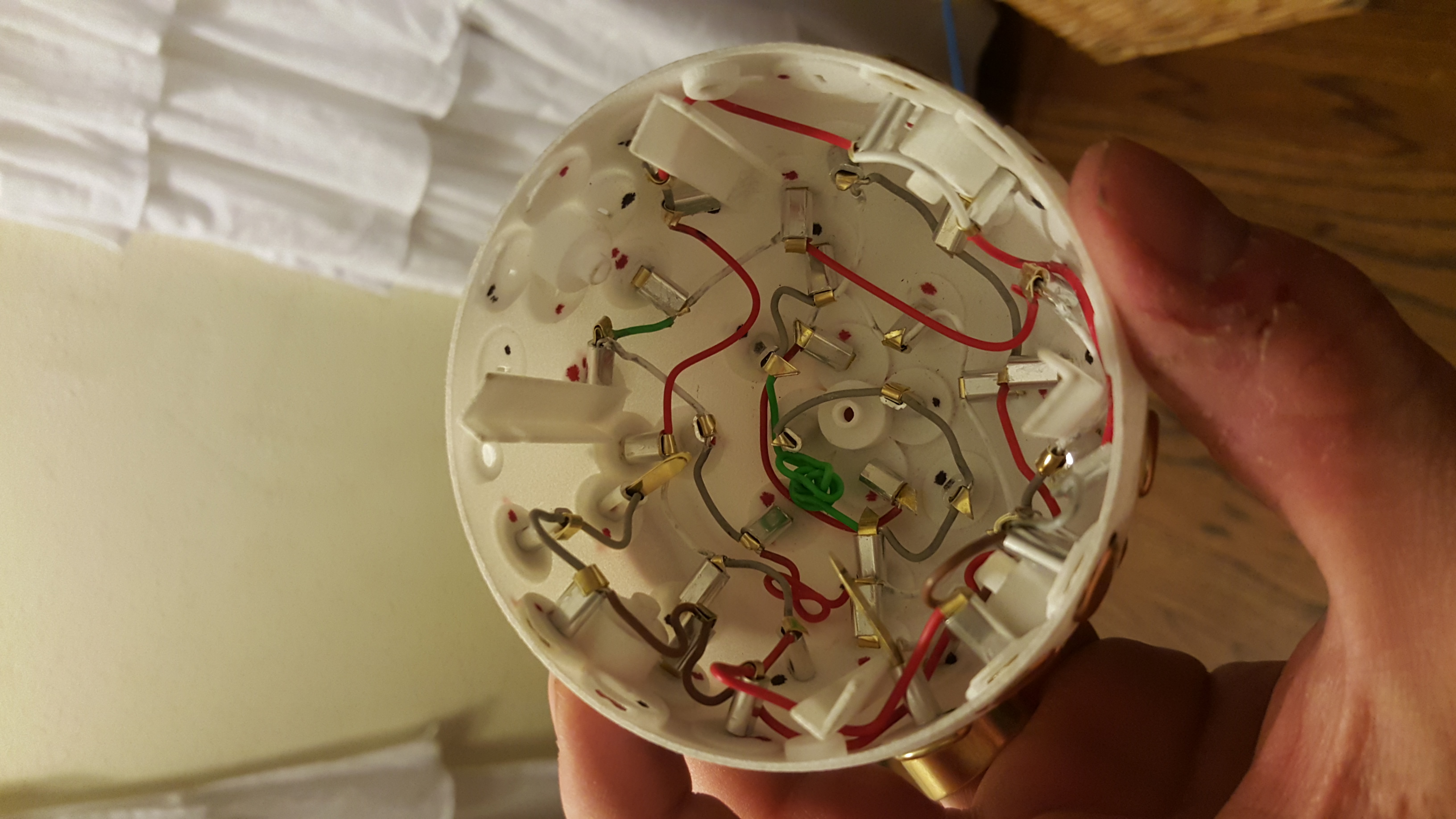
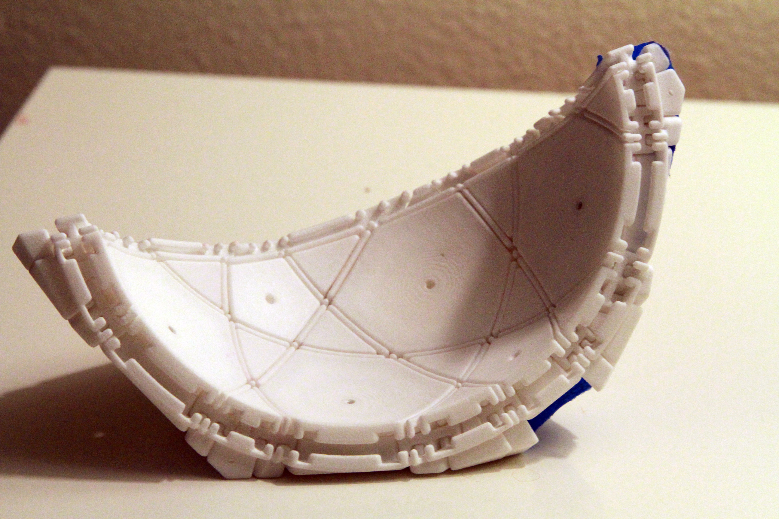
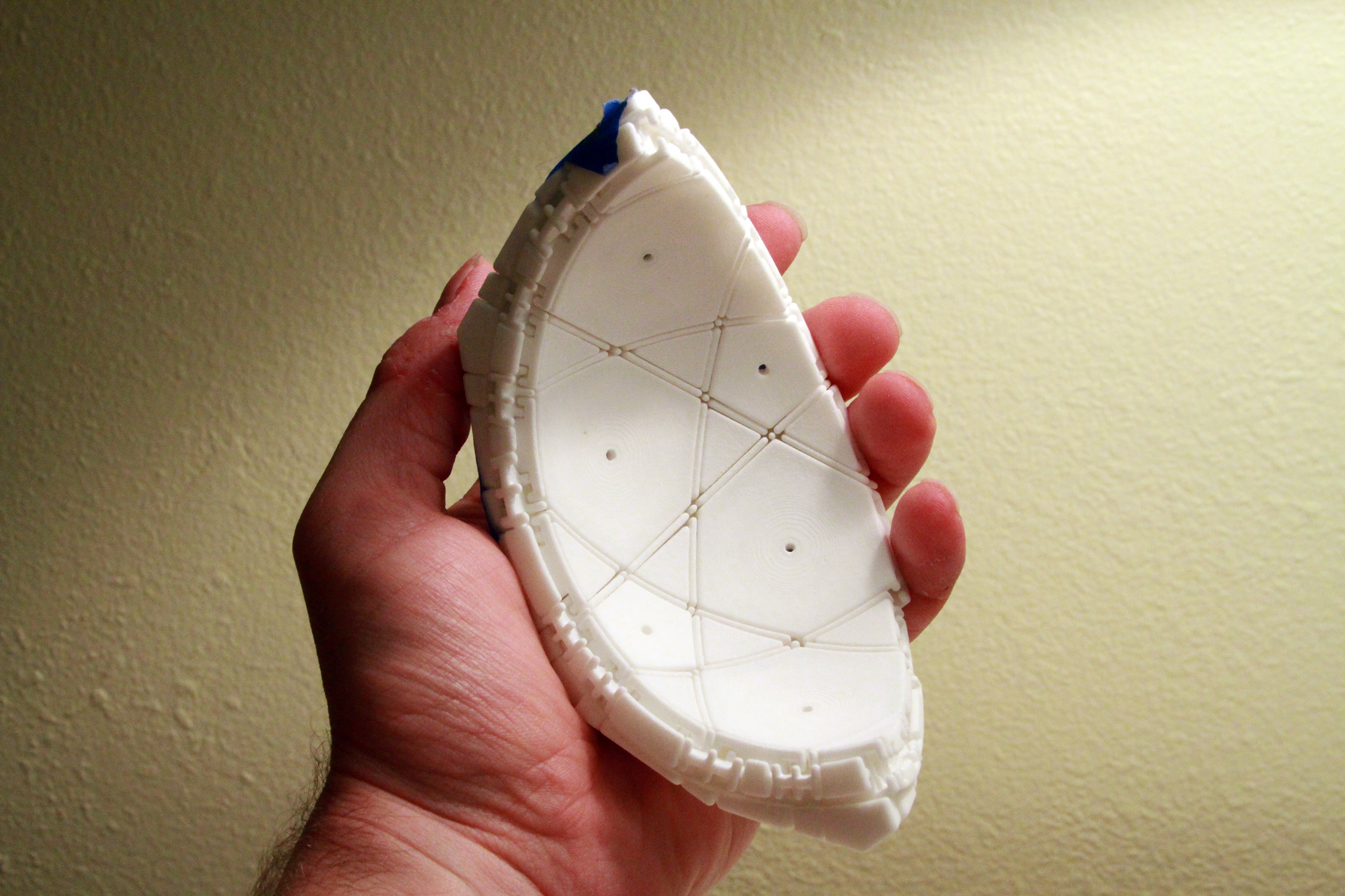
And here’s a finished half. I tested this core for some time to be sure that the connections were good. I found a disconcerting fact. The thickness of the core was 1mm. Of course this was an optimization to keep material cost low. However, I found that the core could flex while working with it, and the flexing was making the connections a little flaky. I think this was mostly a problem between the core and the moving parts, but it became increasingly worrisome.
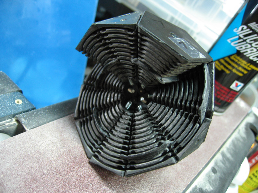
Nonetheless, I proceeded to try to get it to work. It was so promising, but just fell short of being usable once corners were added.

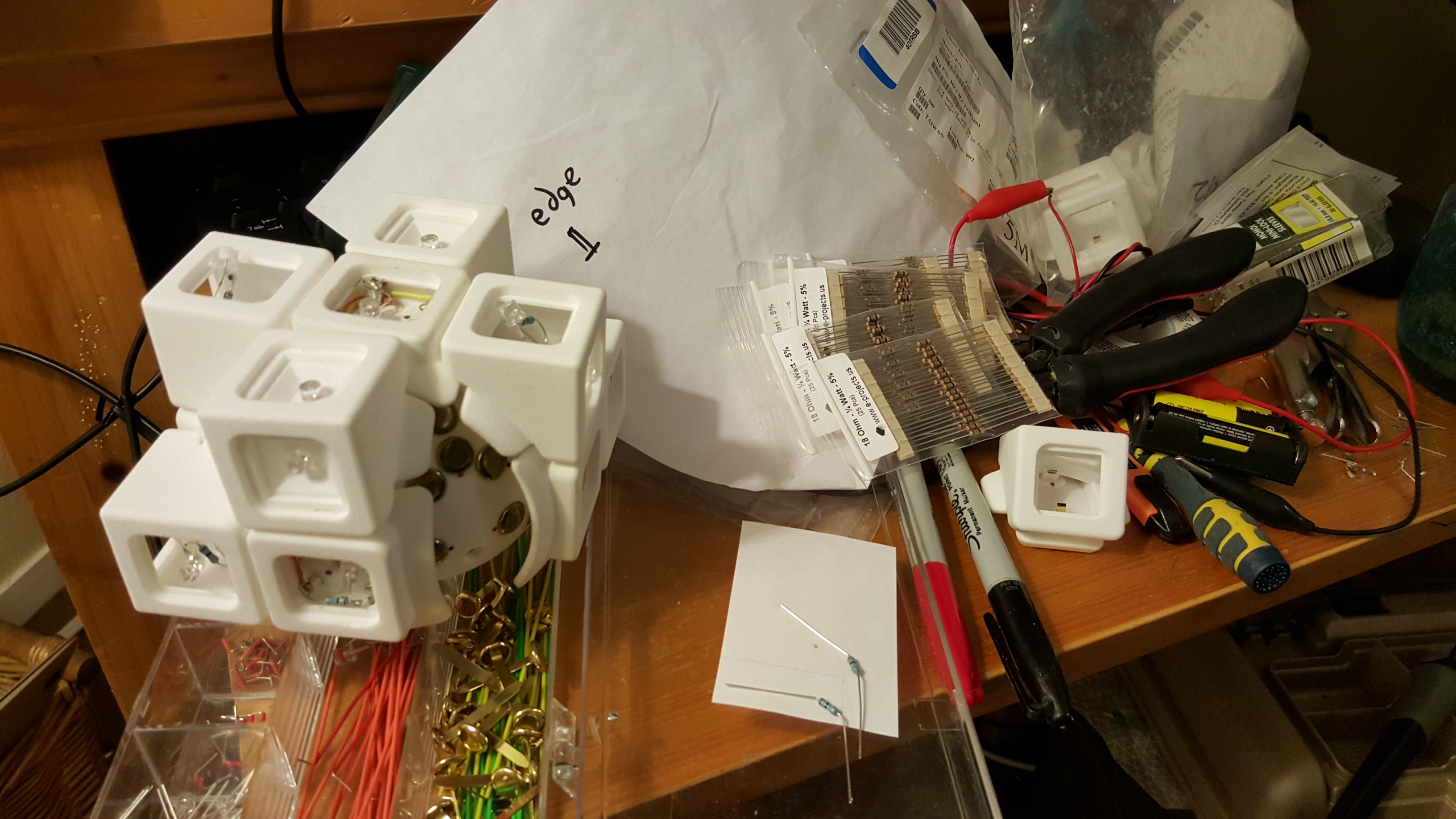
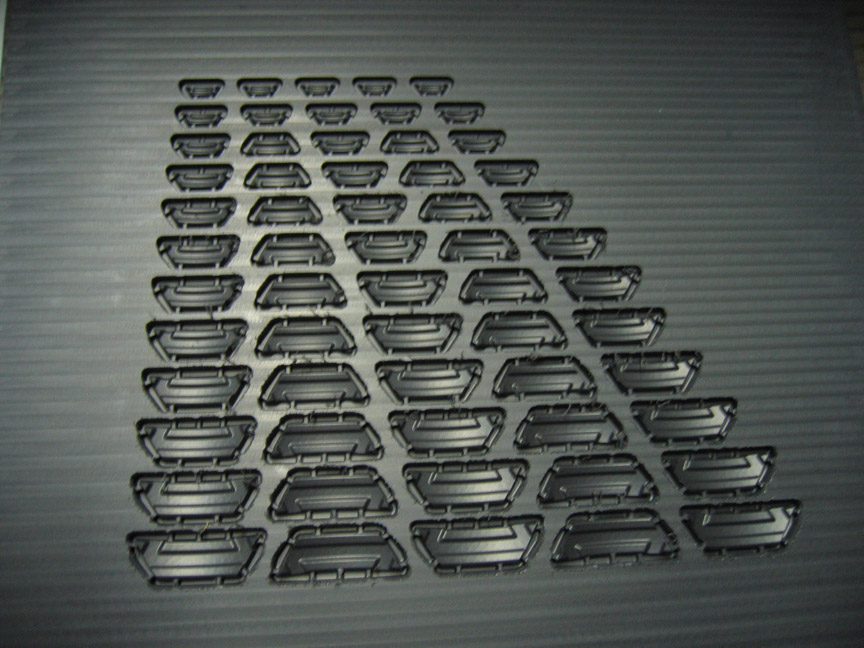
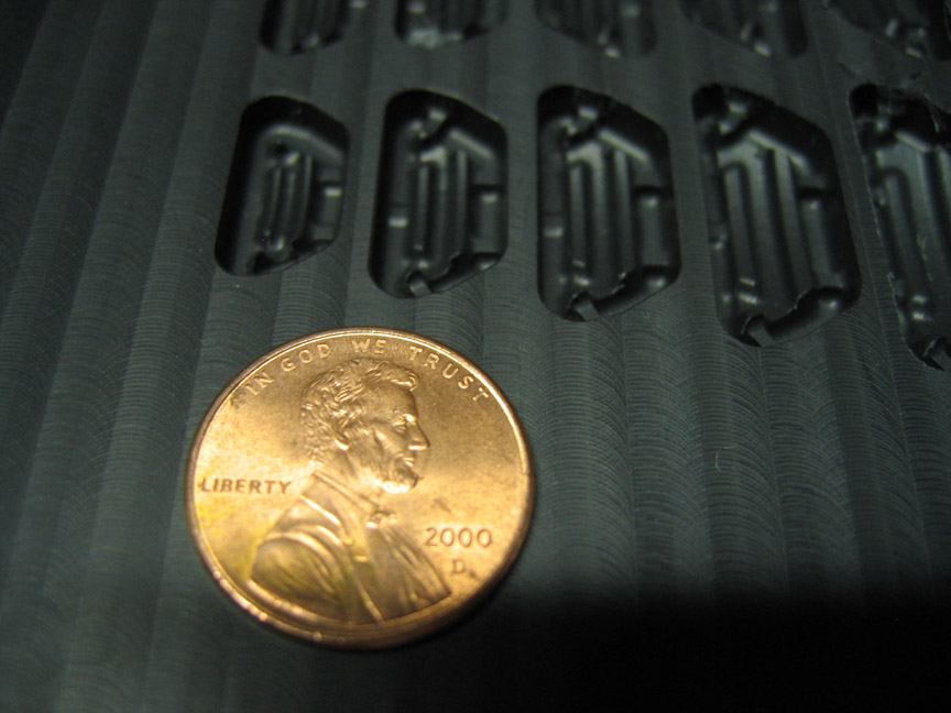
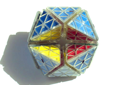
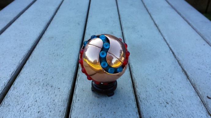
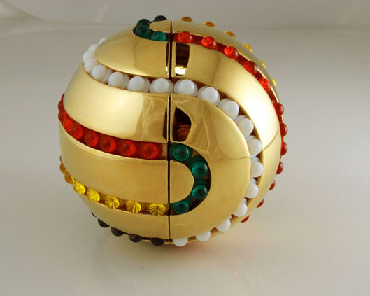
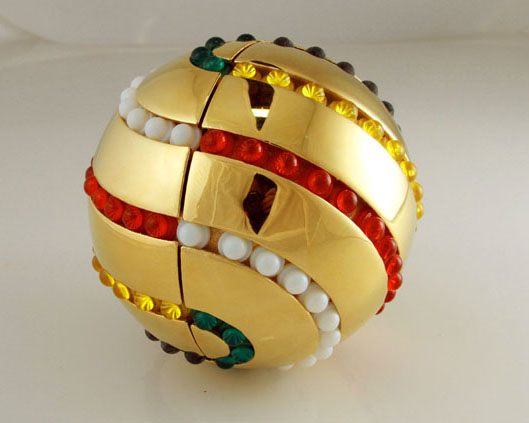
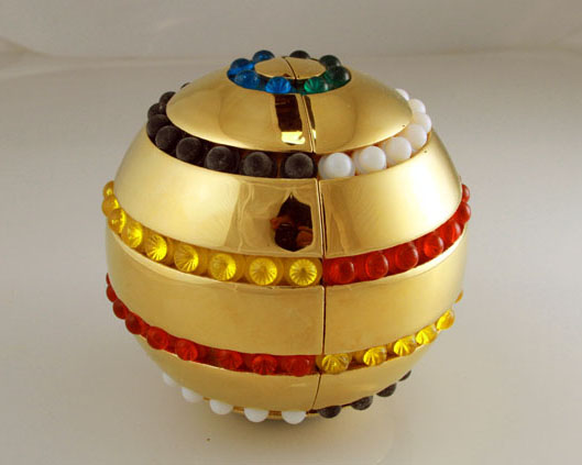
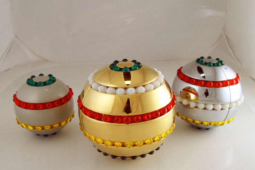
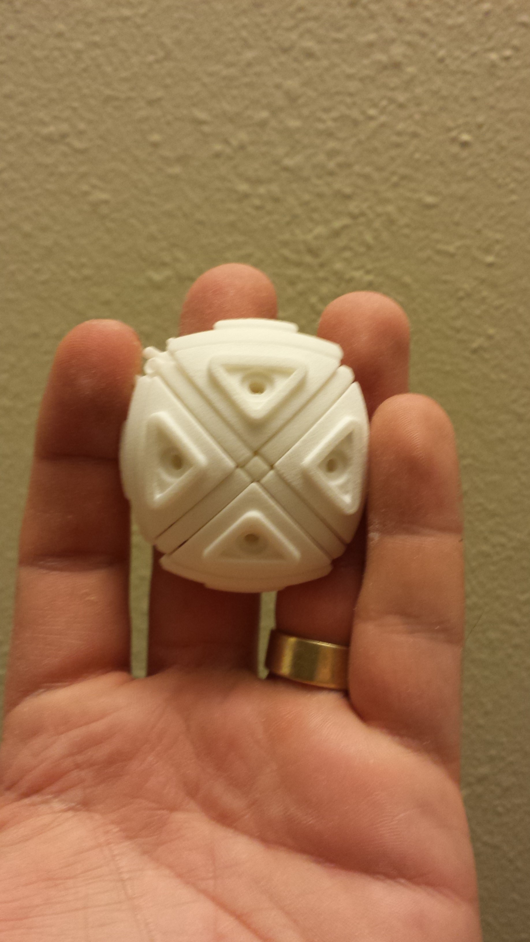
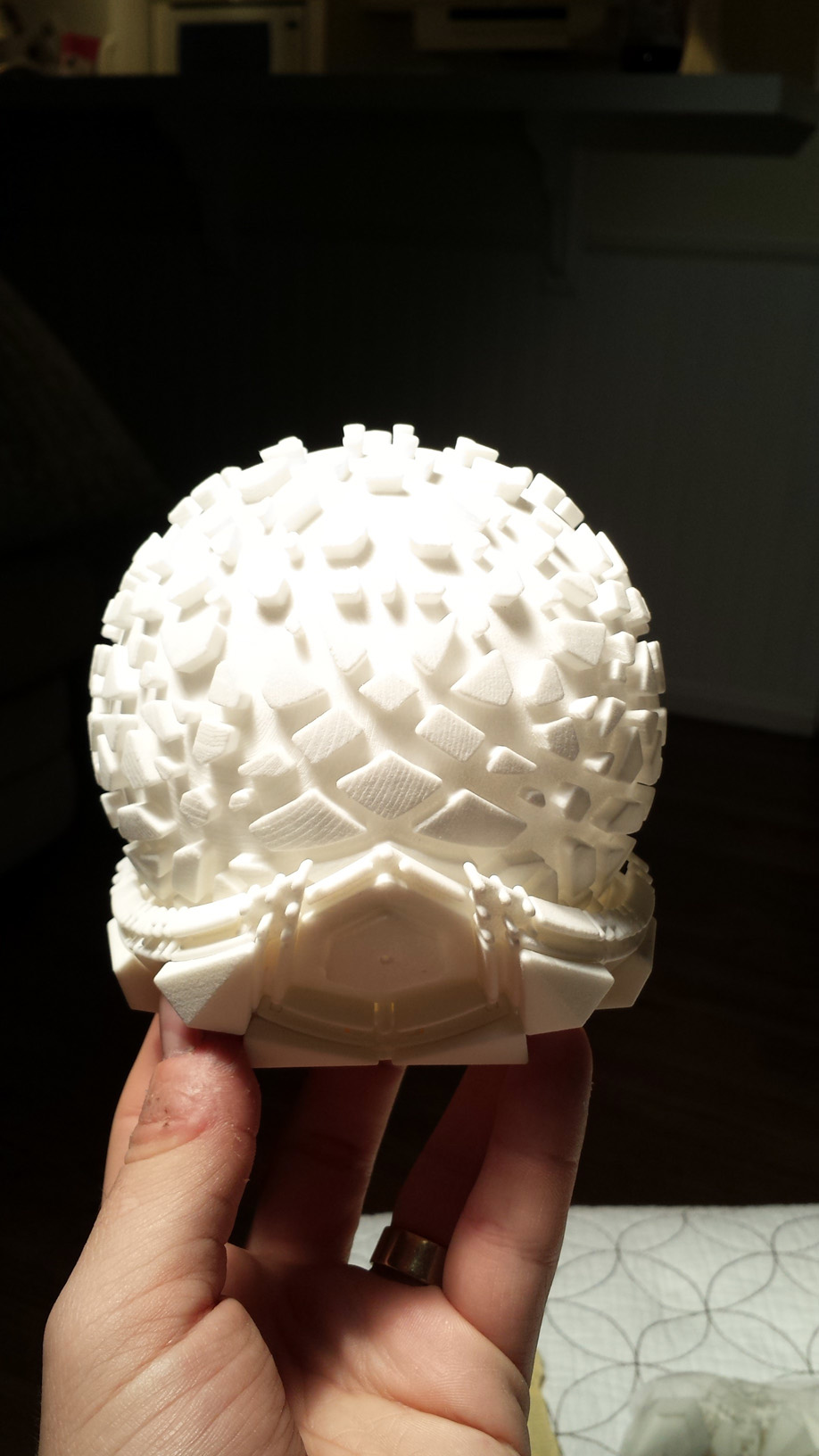
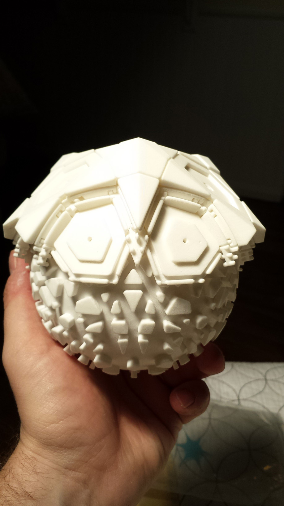
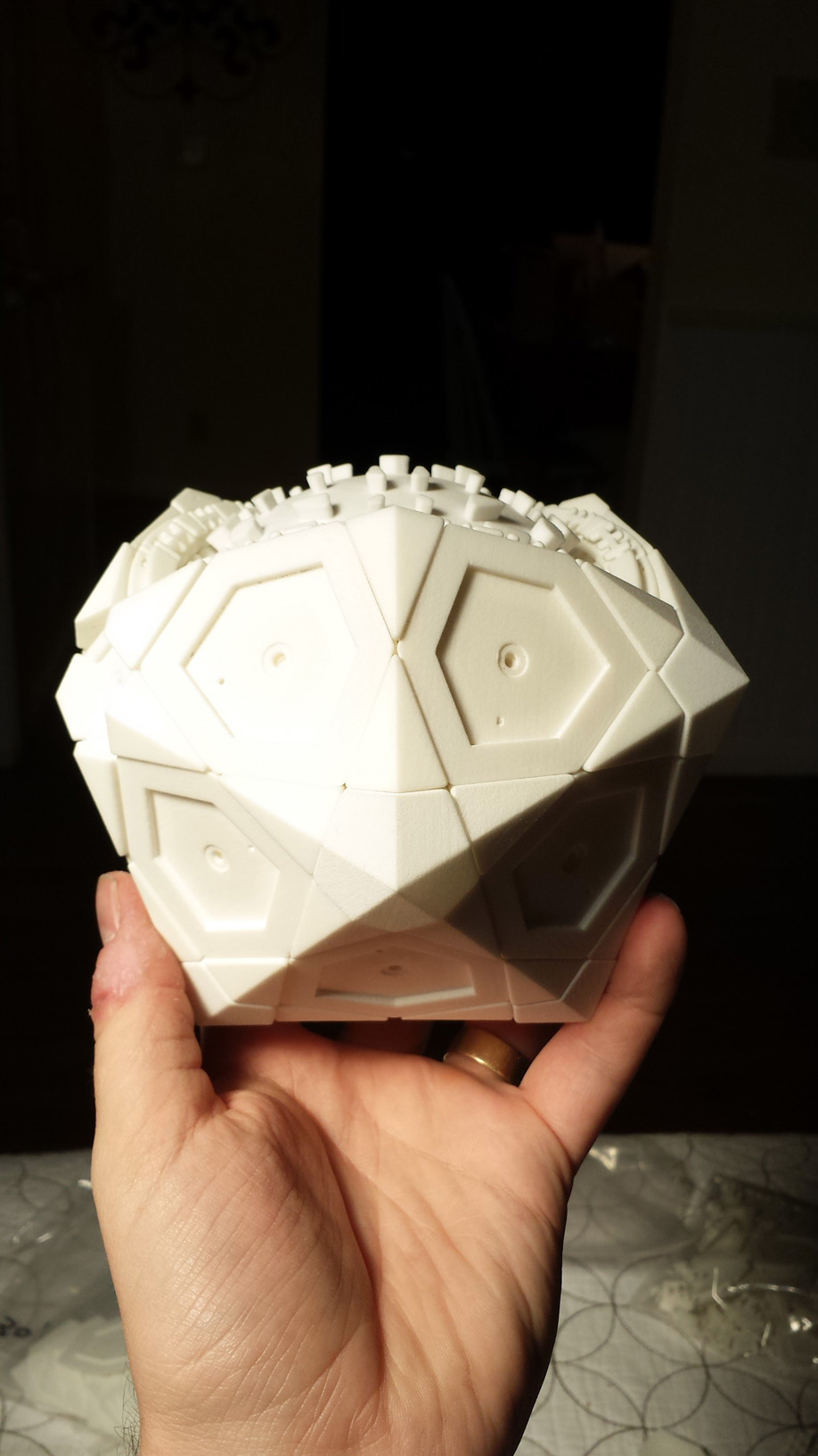
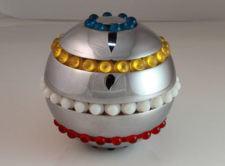
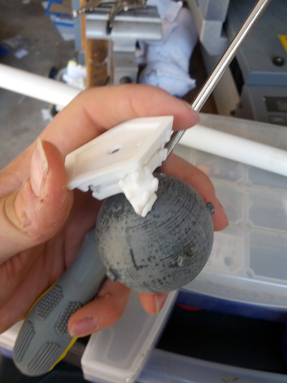
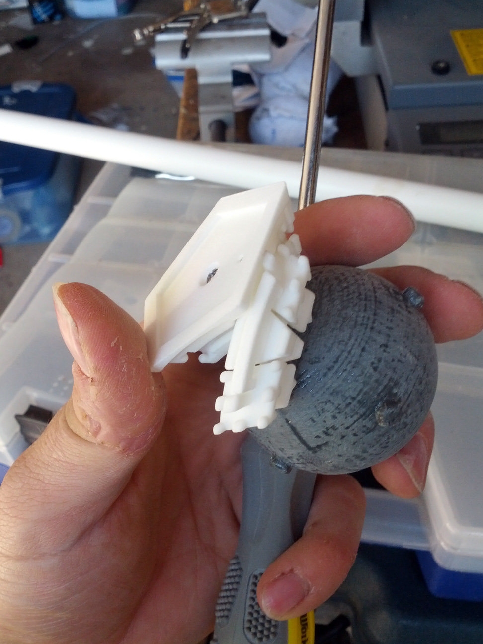
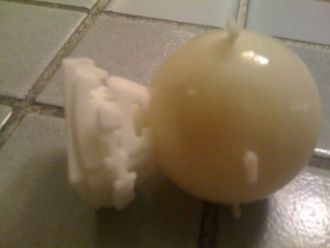
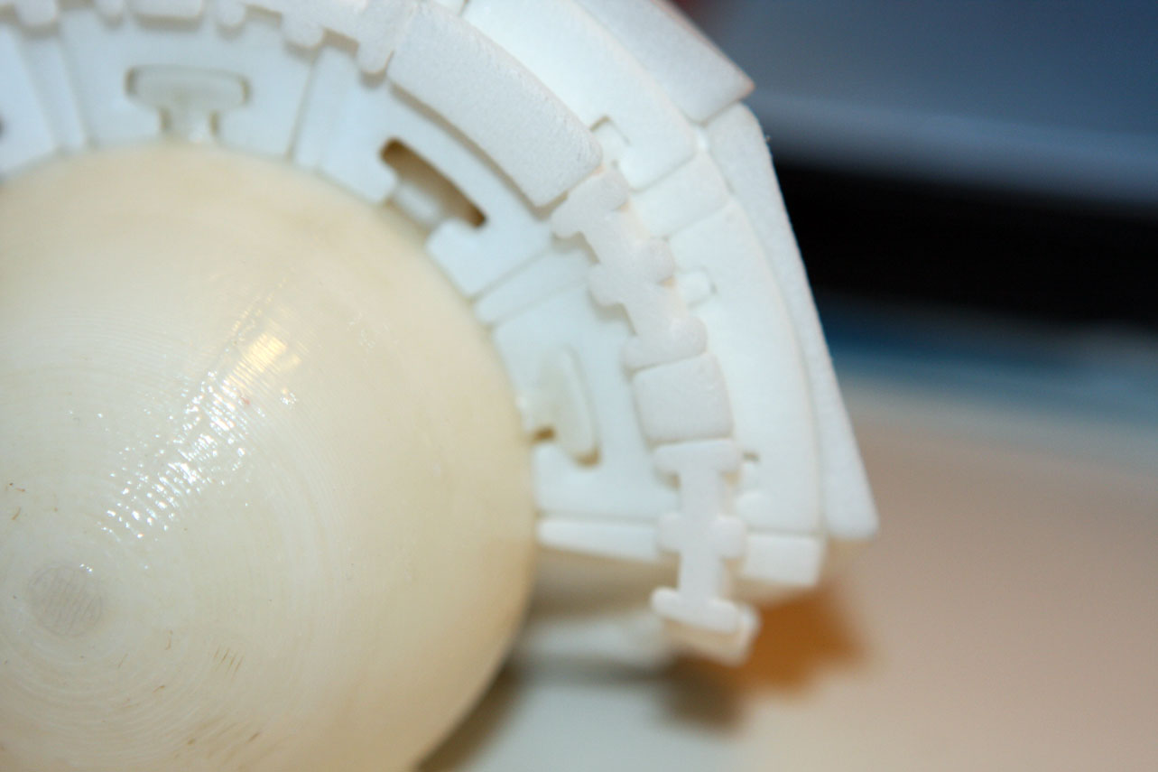
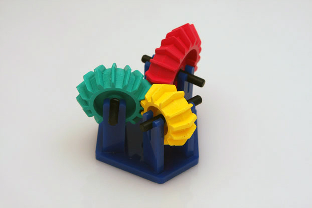
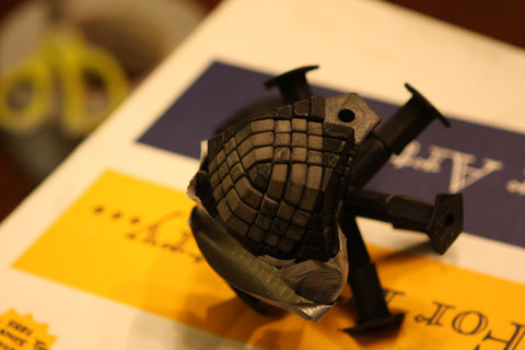
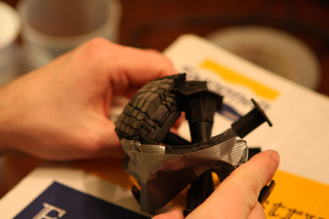
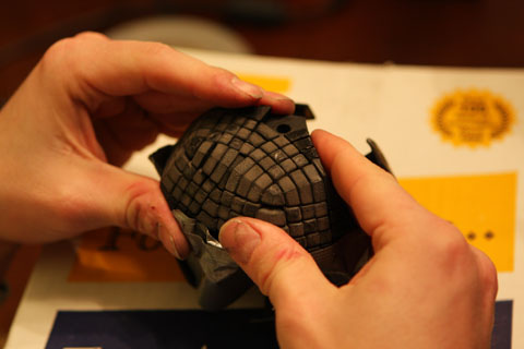
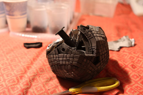
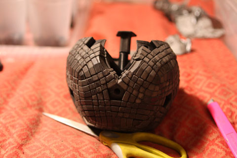
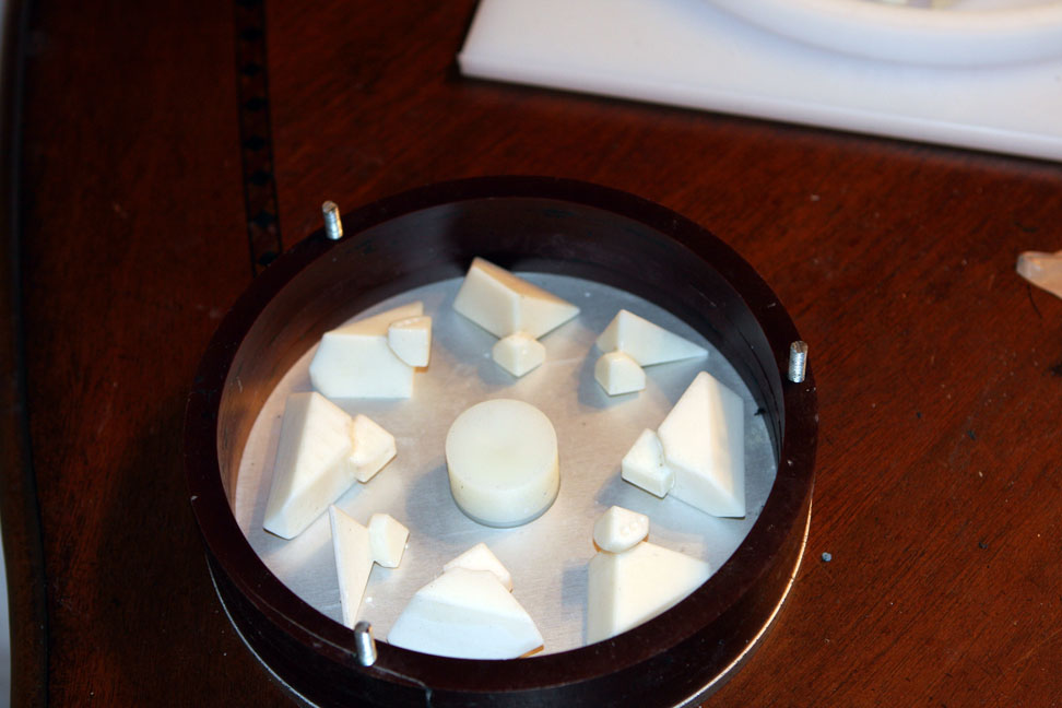
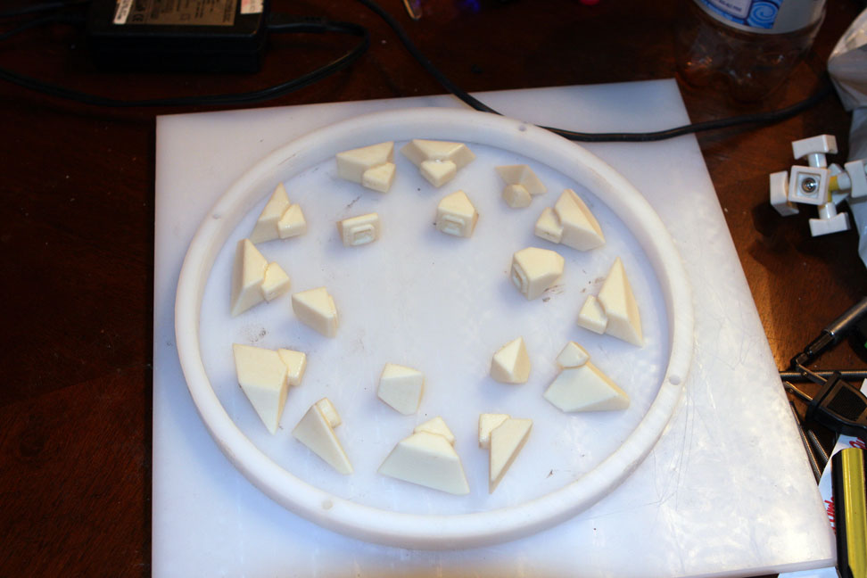
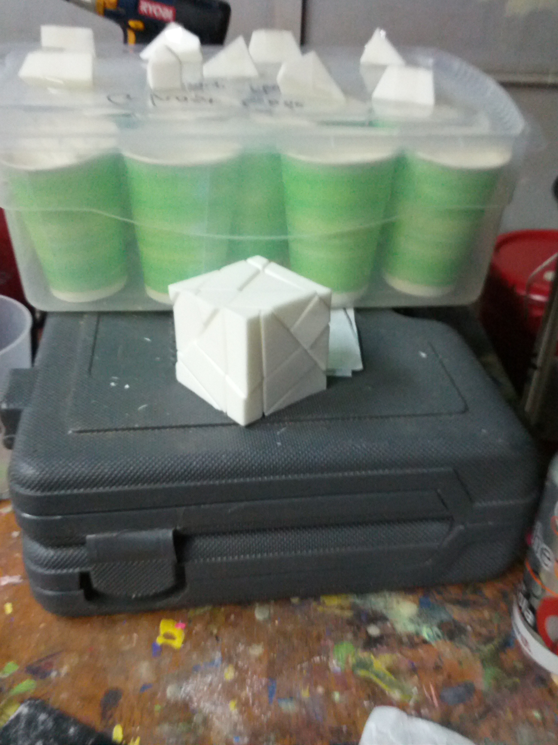
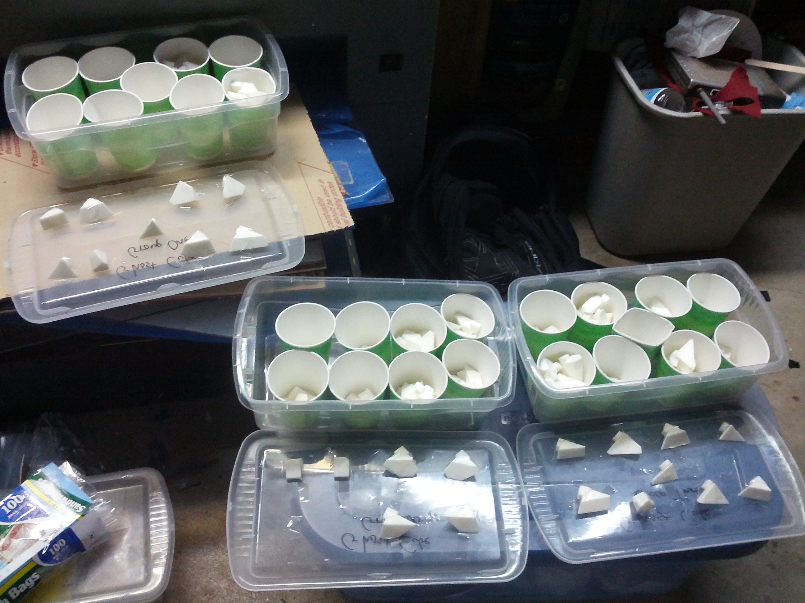
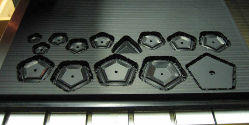
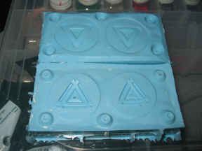
The parts were all designed to mate with rounded glass square tiles from Sun and Moon Crafting Kits.
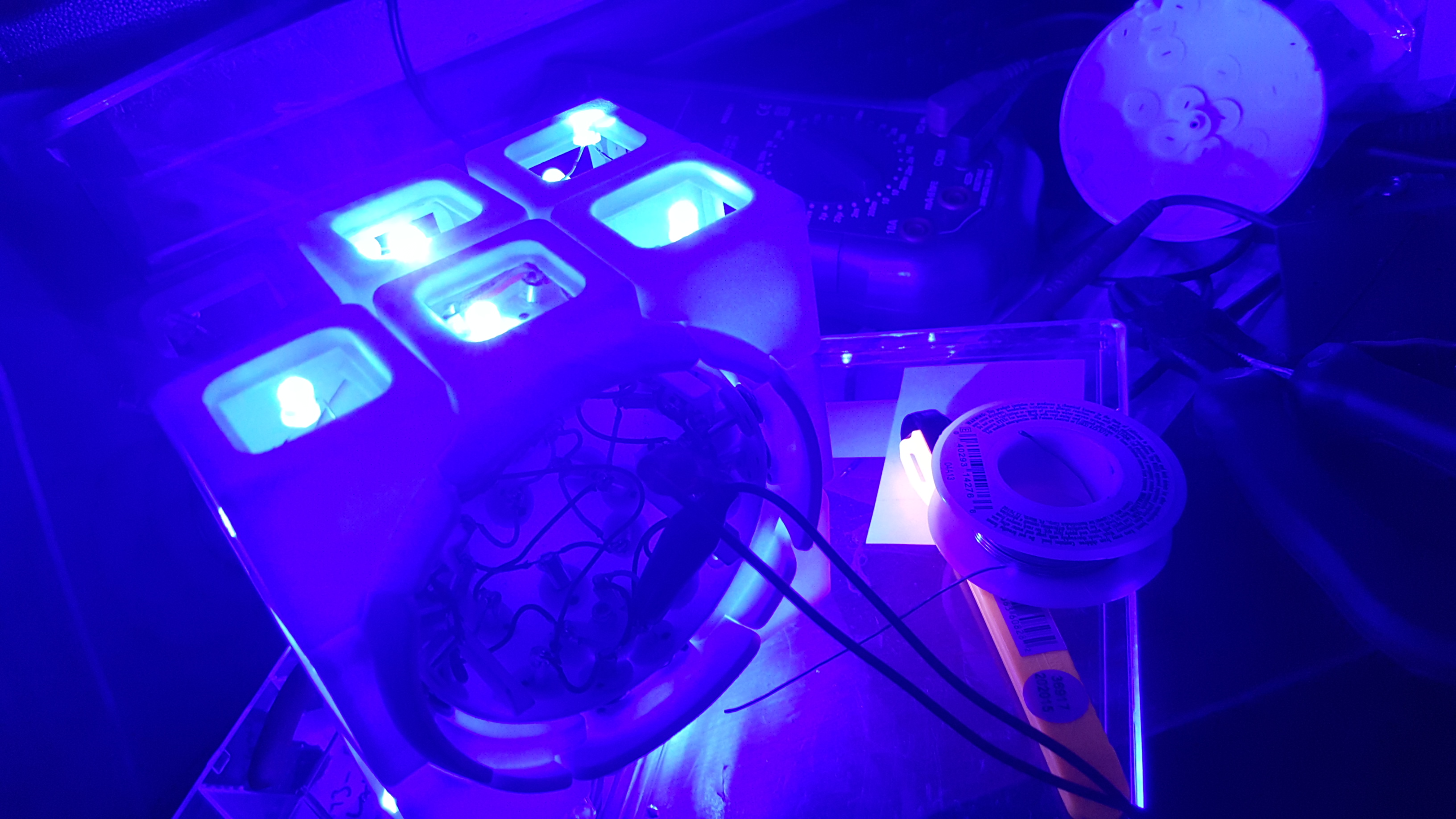
I noticed that many times, the contacts weren’t working when they were very very close to touching. Sometimes, so much so that it looked like they were touching to the naked eye. This would cause the lights to dim or flicker, or even just be off when they should have been on.
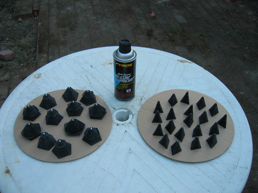
I recognized that oxidization could be a factor, so I tried conducting oil called DeoxIt.
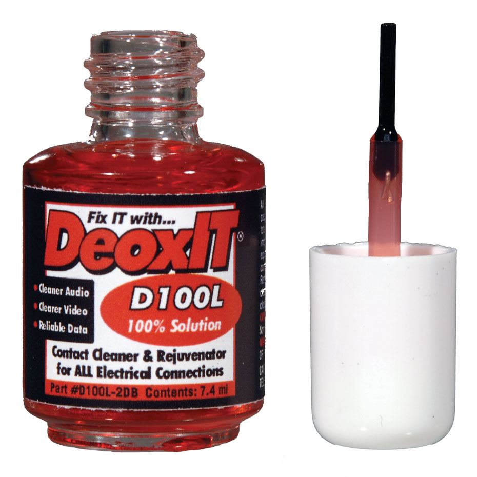
DeoxIt dissolves minor oxidization and helps prevent future issues. It did help, but in the end, it became clear that this design would always feel unreliable even at its best.
I realized that since the contacts were already so close to touching, they just needed a little attraction in order to pull together.
Version 5 – 2016
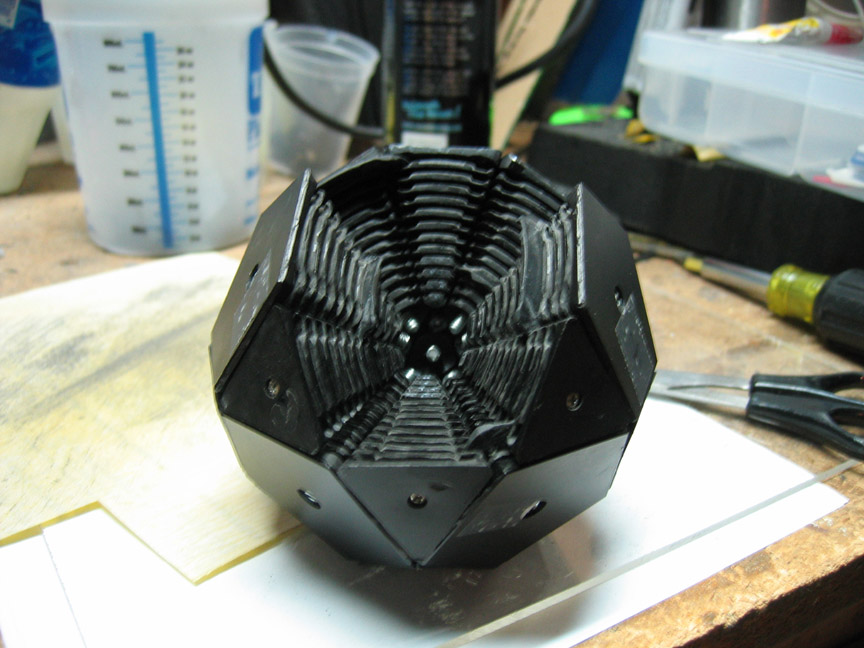
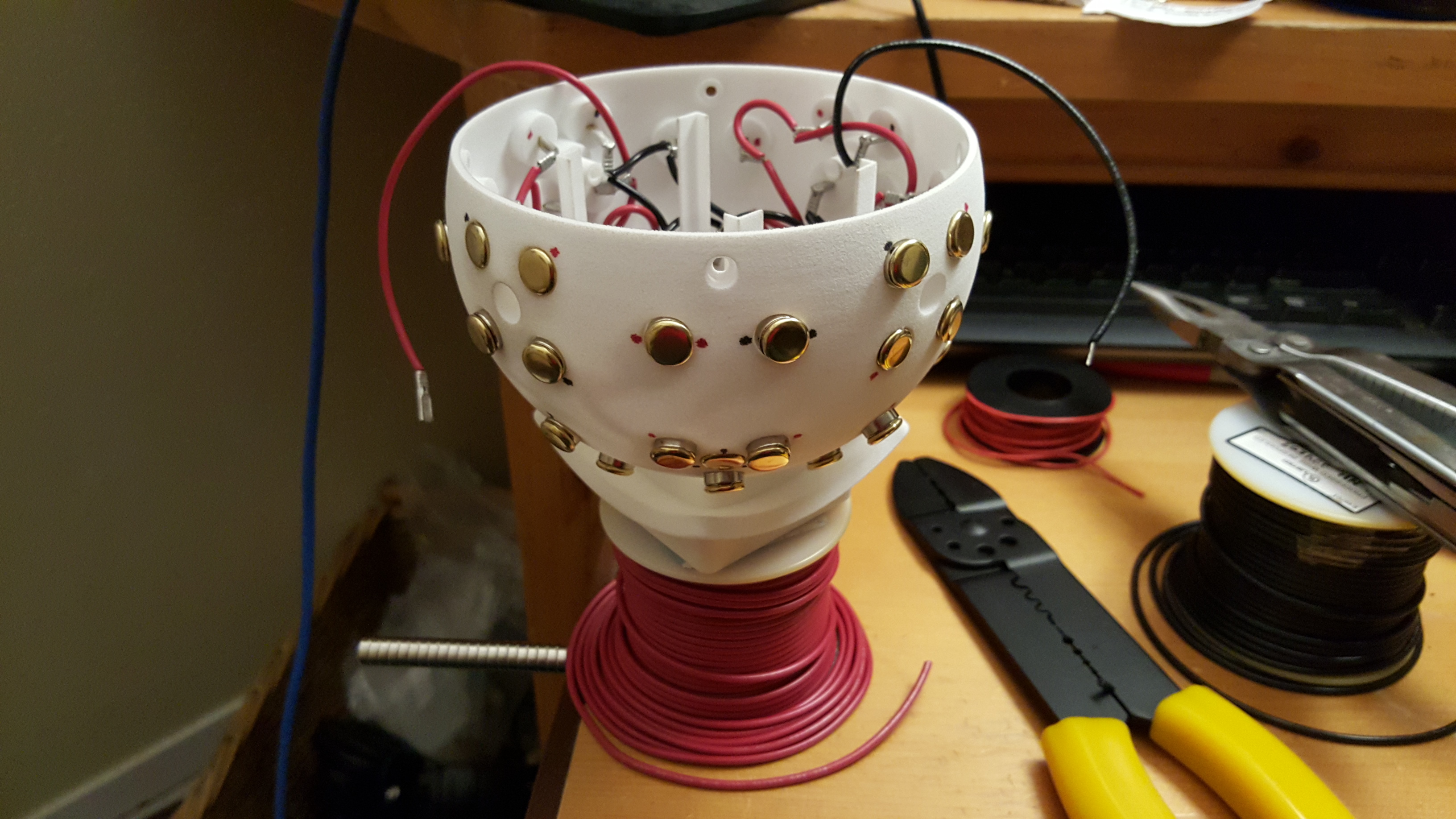
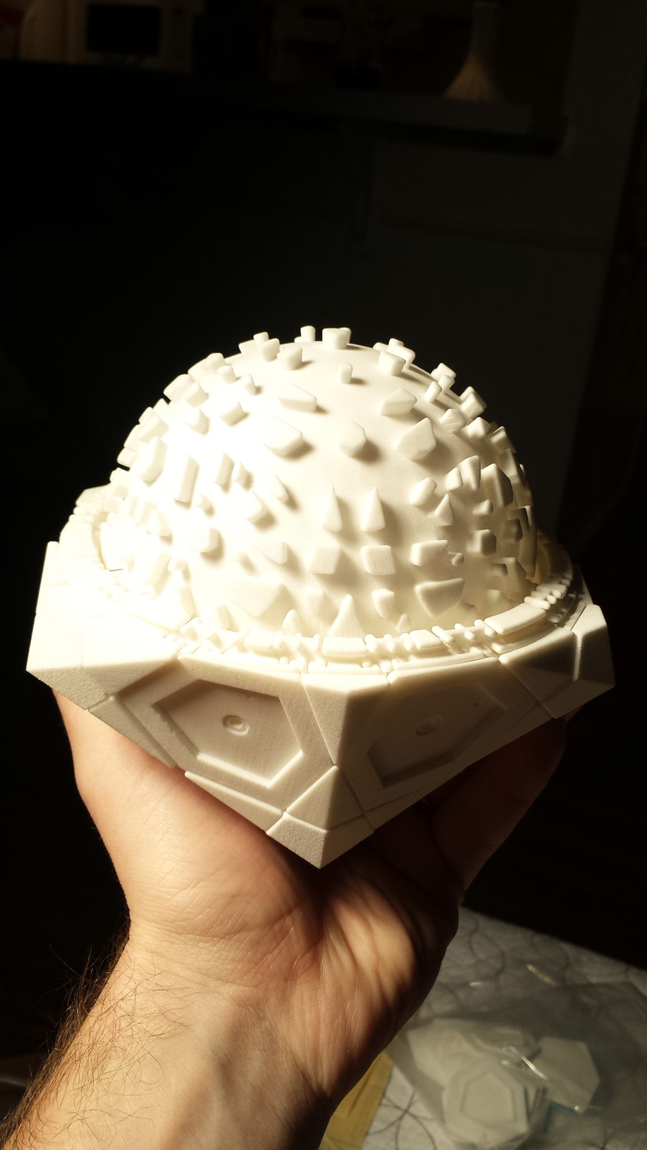
I had the idea of using neodymium ring magnets behind the brad heads. Once the brad heads approached each other, the neodymium magnets would be attracted and help create pressure on the contact.
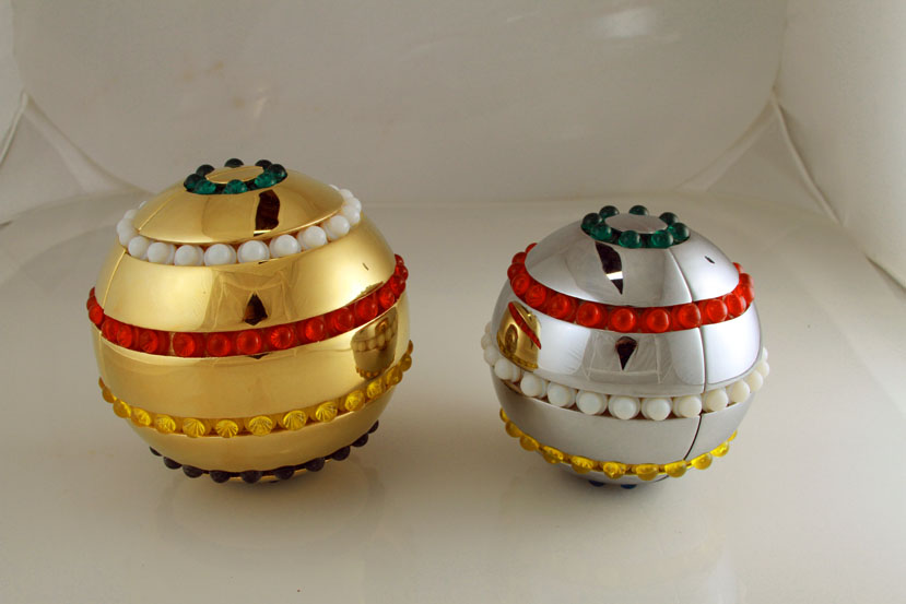
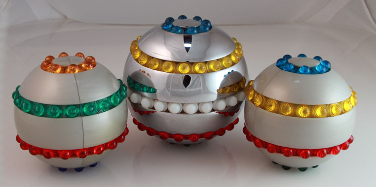
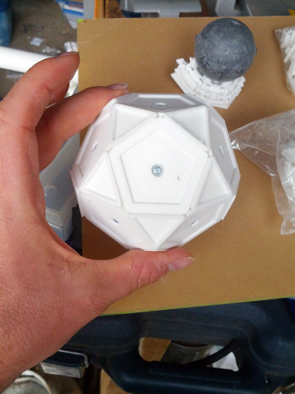
In order to do this, the entire puzzle had to be increased in size to make room for the magnets.
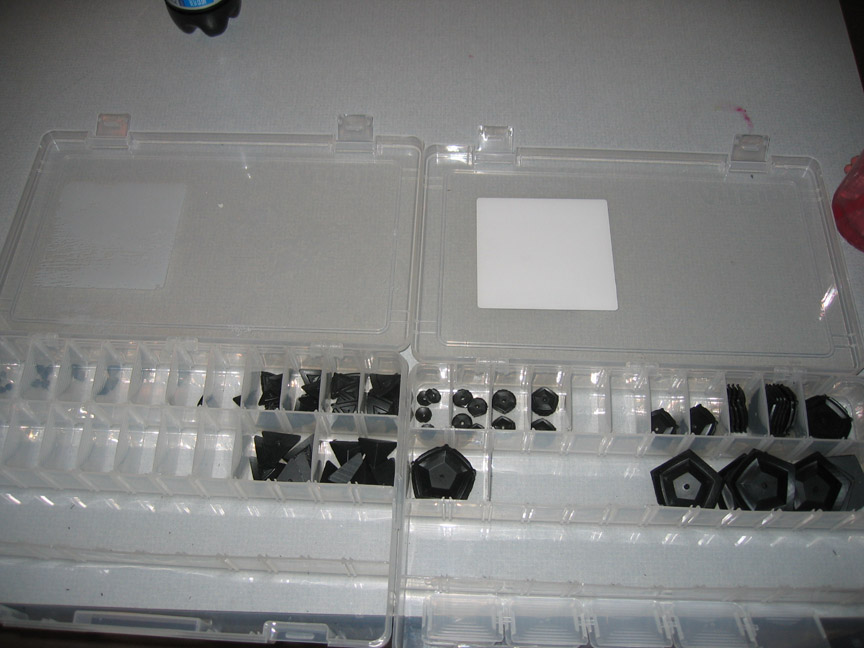
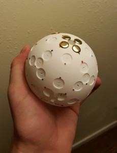
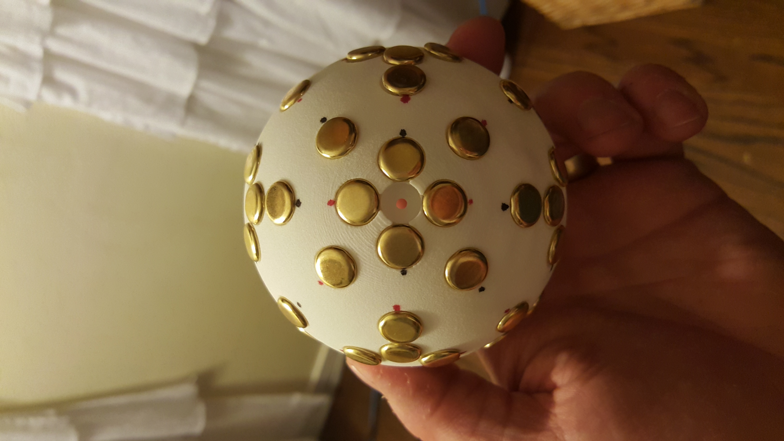
I found neodymium ring magnets the right size to slip the leg of the brad through, so the magnet could line up behind the round brad head. The supplier was K&J Magnetics.
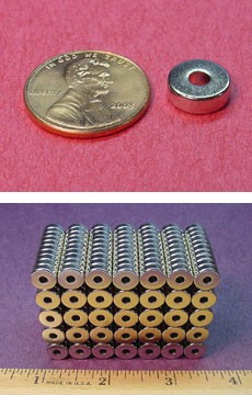
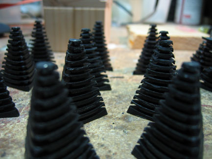
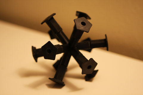
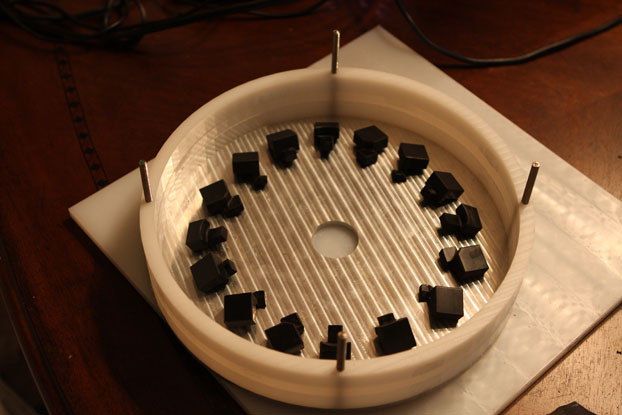
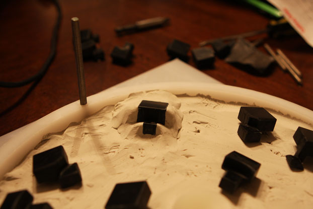
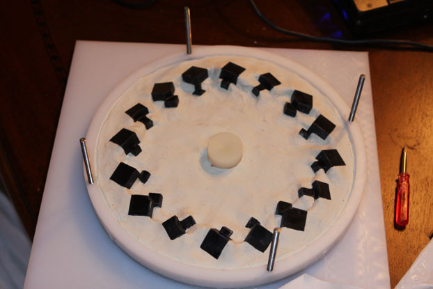
Once I received the magnets, I created some trimmed brads with magnets applied, and stored them on a nearby lamp. Otherwise, they would fly across the desk to make contact with each other!
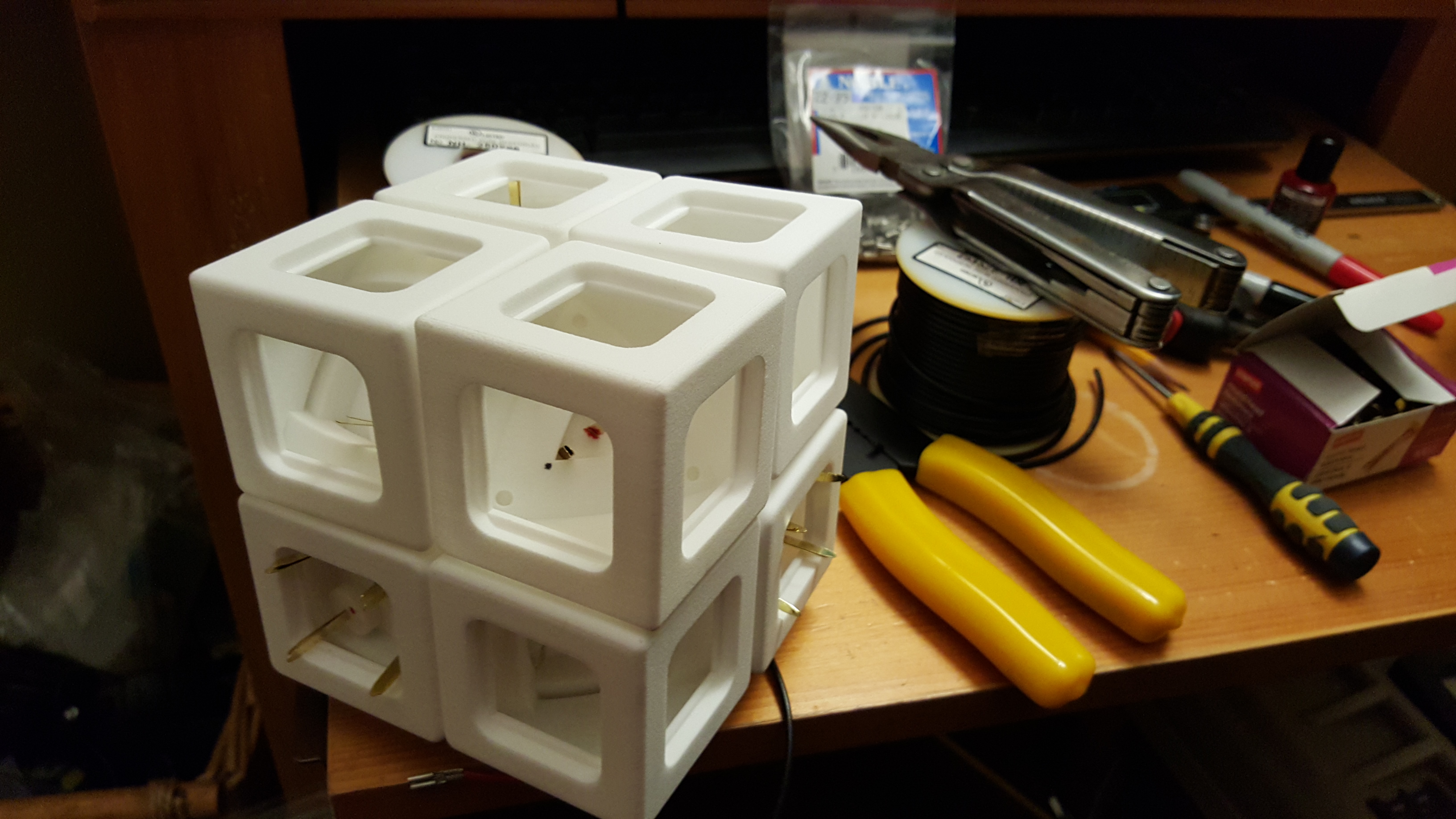
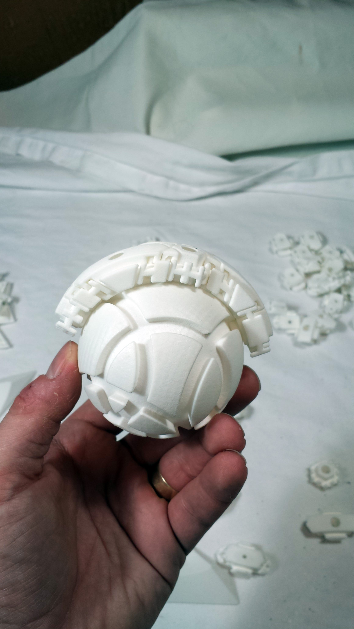
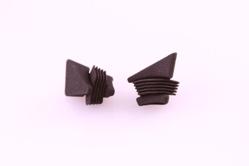
The core was modified to make the depressions for the brads deeper to allow for the magnets. The walls of the core were also thickened to 2mm! The hope was that a thicker core would be less likely to flex and break contacts.
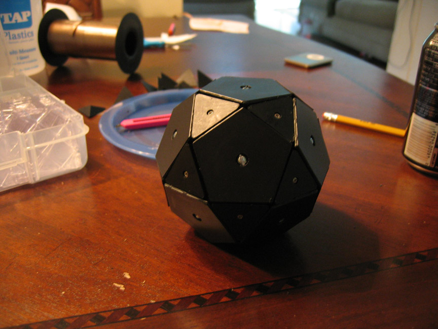
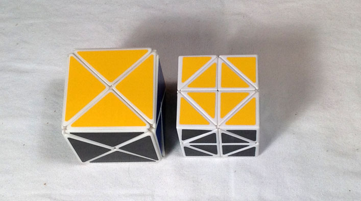
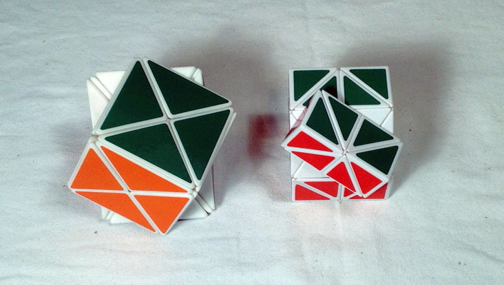
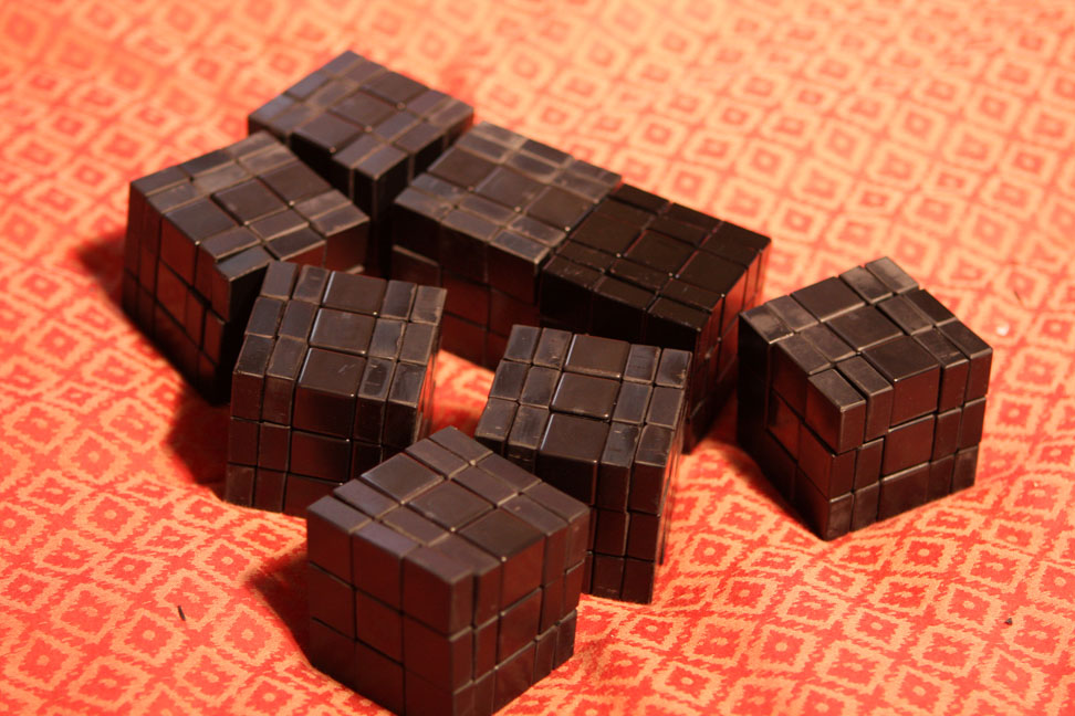
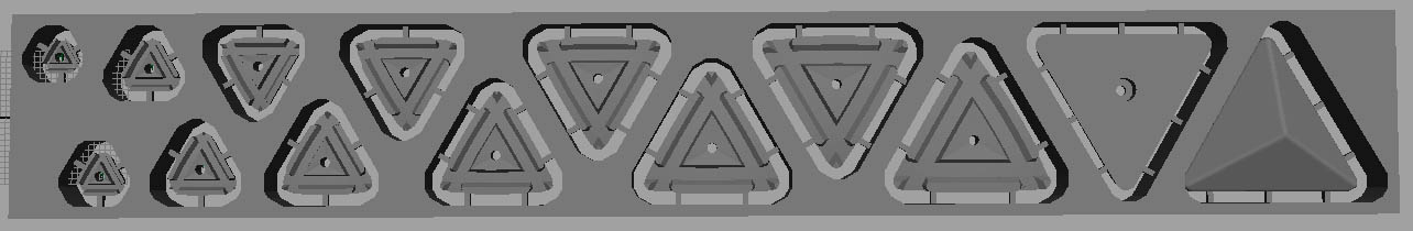
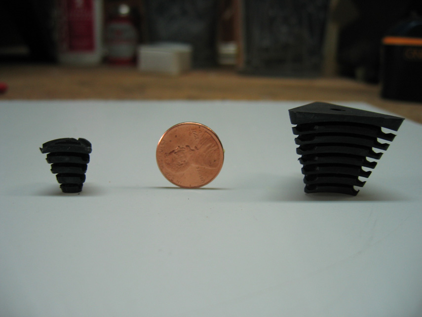
At the same time, I decided to use the increased size to simplify the design. Tracks would no longer be needed for the brad insertion, for example! The larger sized parts allowed me to position the contacts such that the brad legs could come straight up into the parts without bending around any corners. The size difference was significant, though!
Also, I made all walls on the moving parts 2mm thick, so that flexing and squishiness would no longer be a problem.
Again, I began by marking the core with polarity marks.
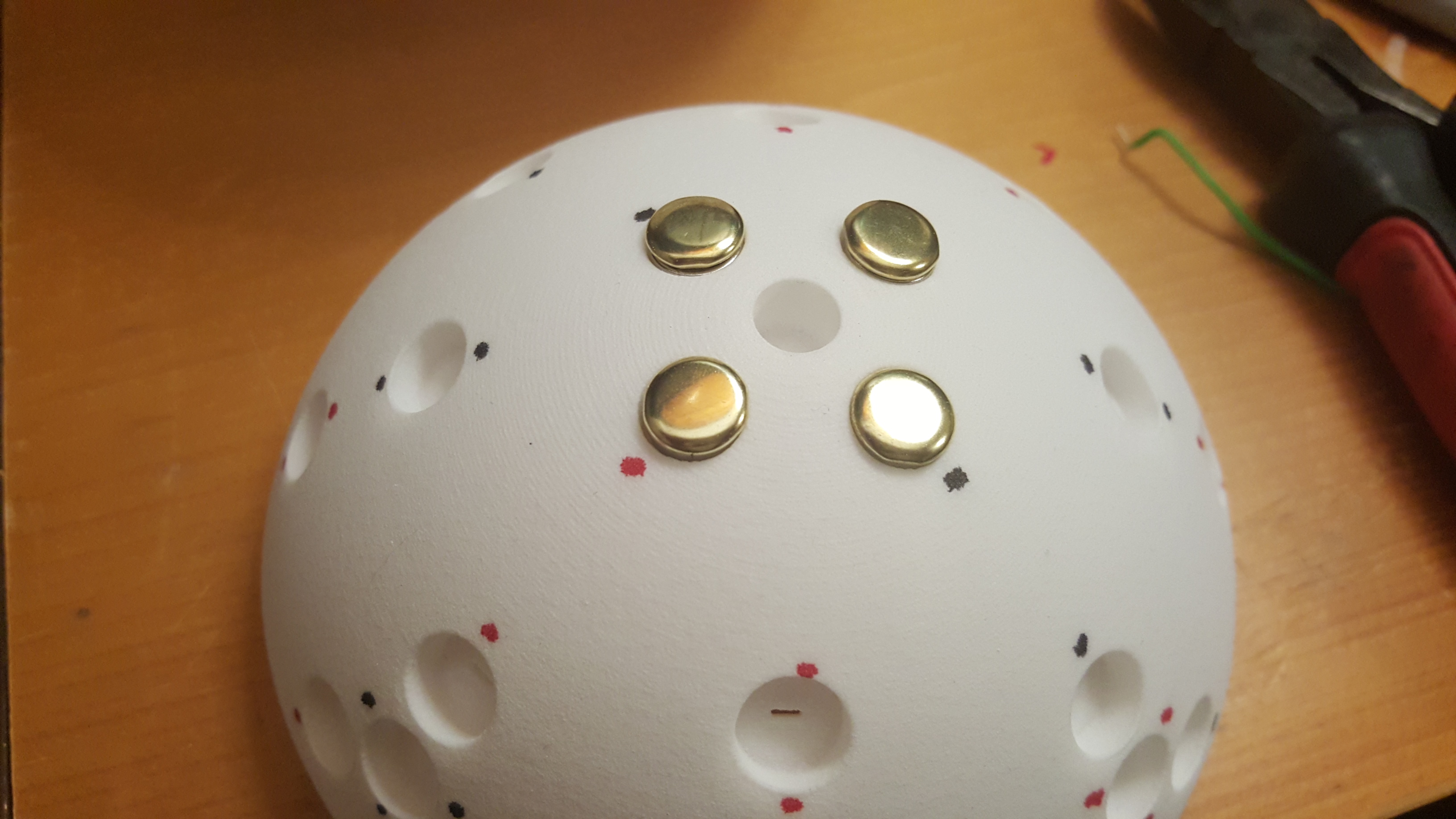
And then it was time to start adding the brads.
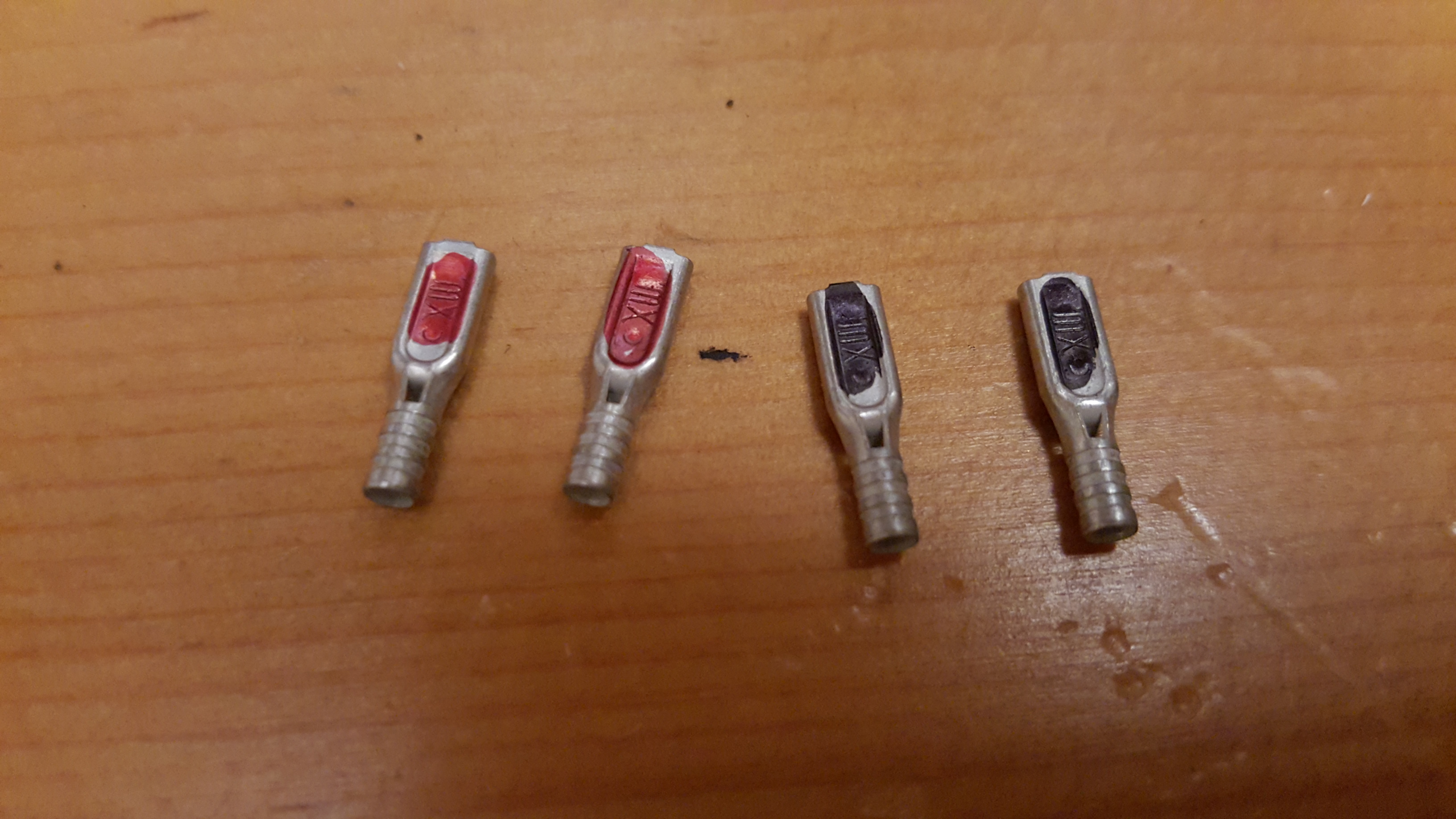
I was still using the fishing crimps, and I decided it was worth one last look to see if I could find some kind of crimp that was designed to make an electrical connection, so I wouldn’t have to solder these hundreds of connections.
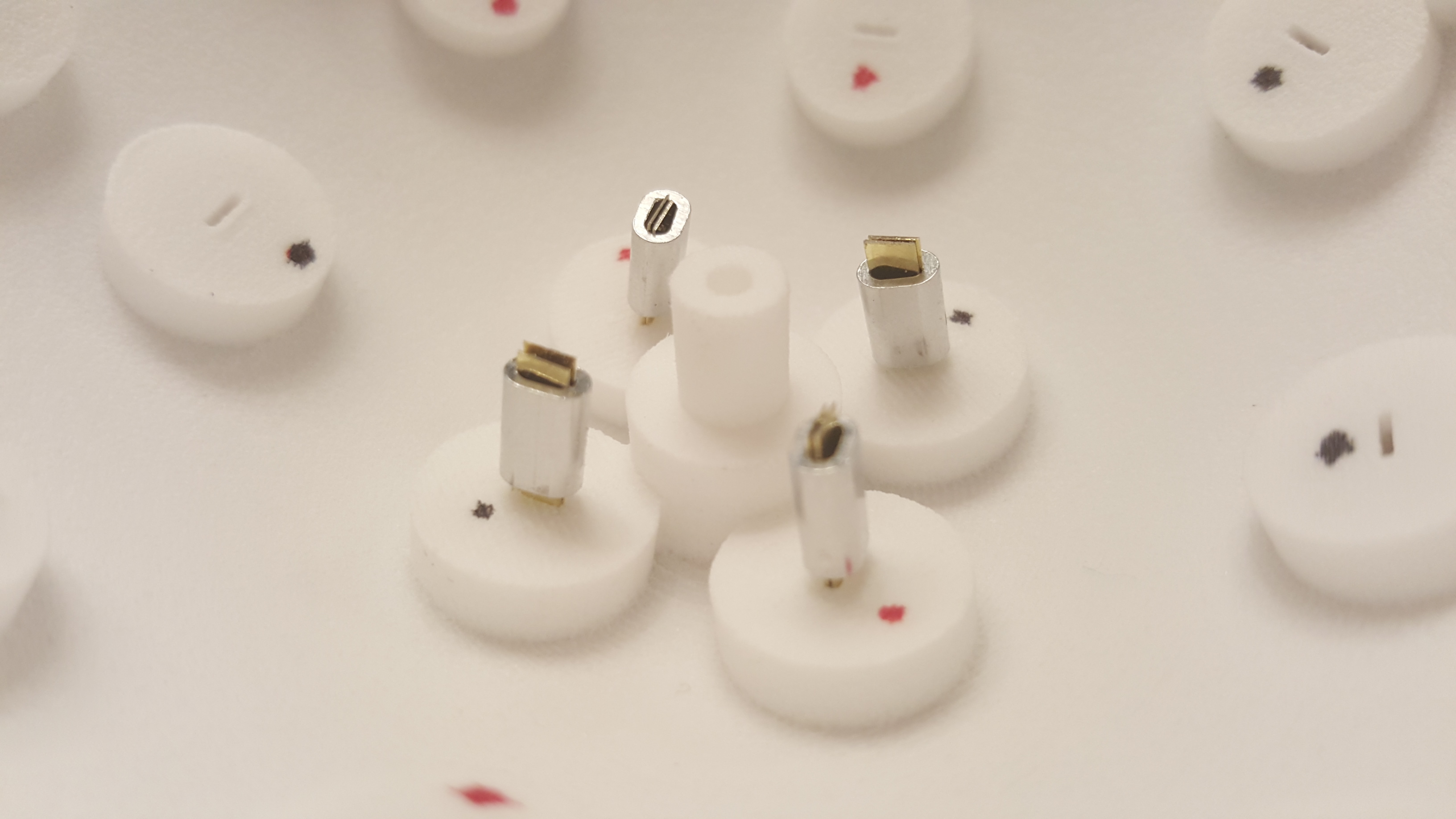
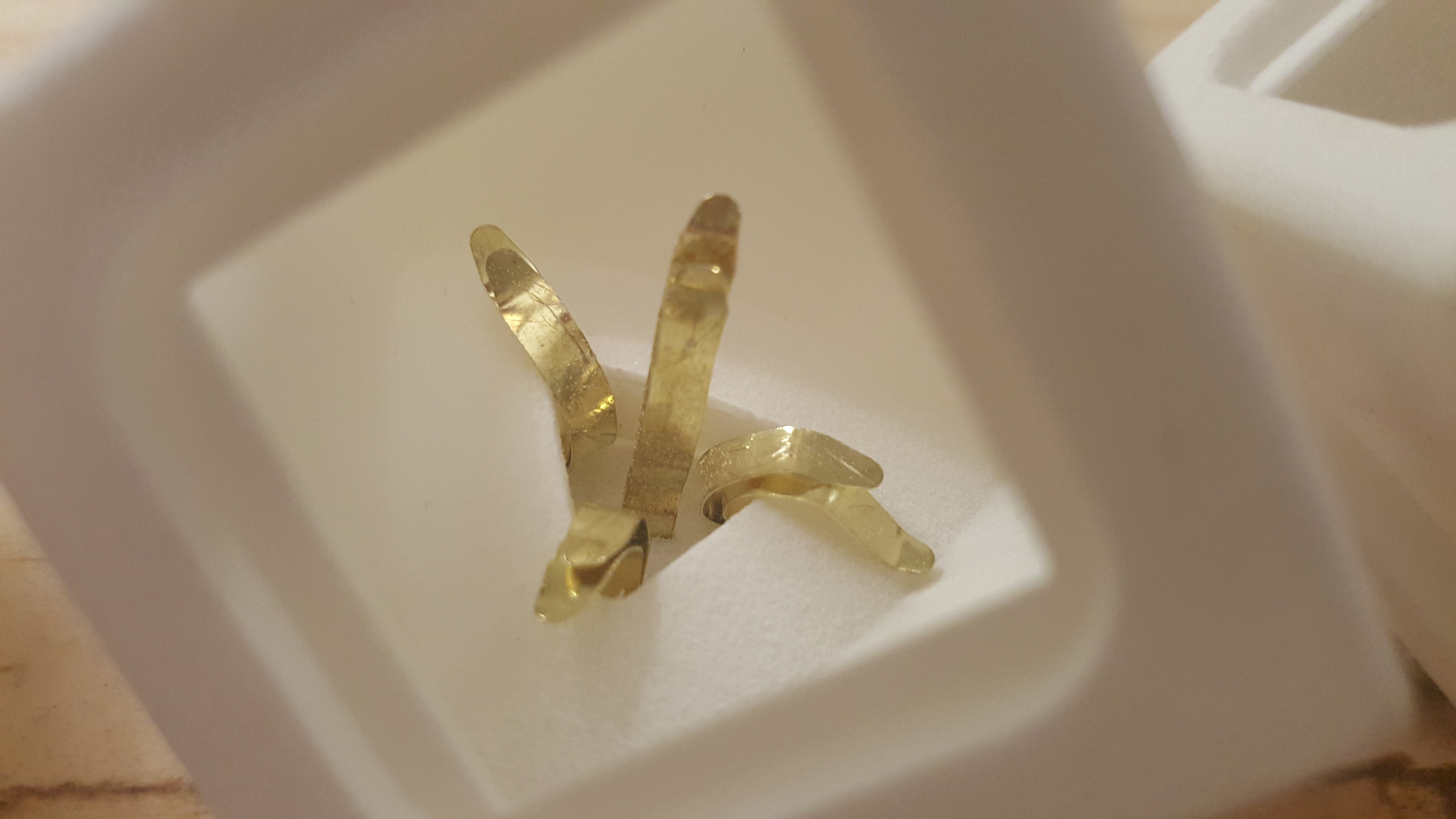
I ended up finding something called spade terminals, which act like they were made to slide onto the legs of a brad and make a great electrical connection, no solder required!
They worked perfectly!
To assemble the centers, I prepared the different parts first. I colored the spade terminals with sharpie to make the polarity simpler to see. I had also purchased nicer red and black wire by this time, so that things would be clearer to look at.
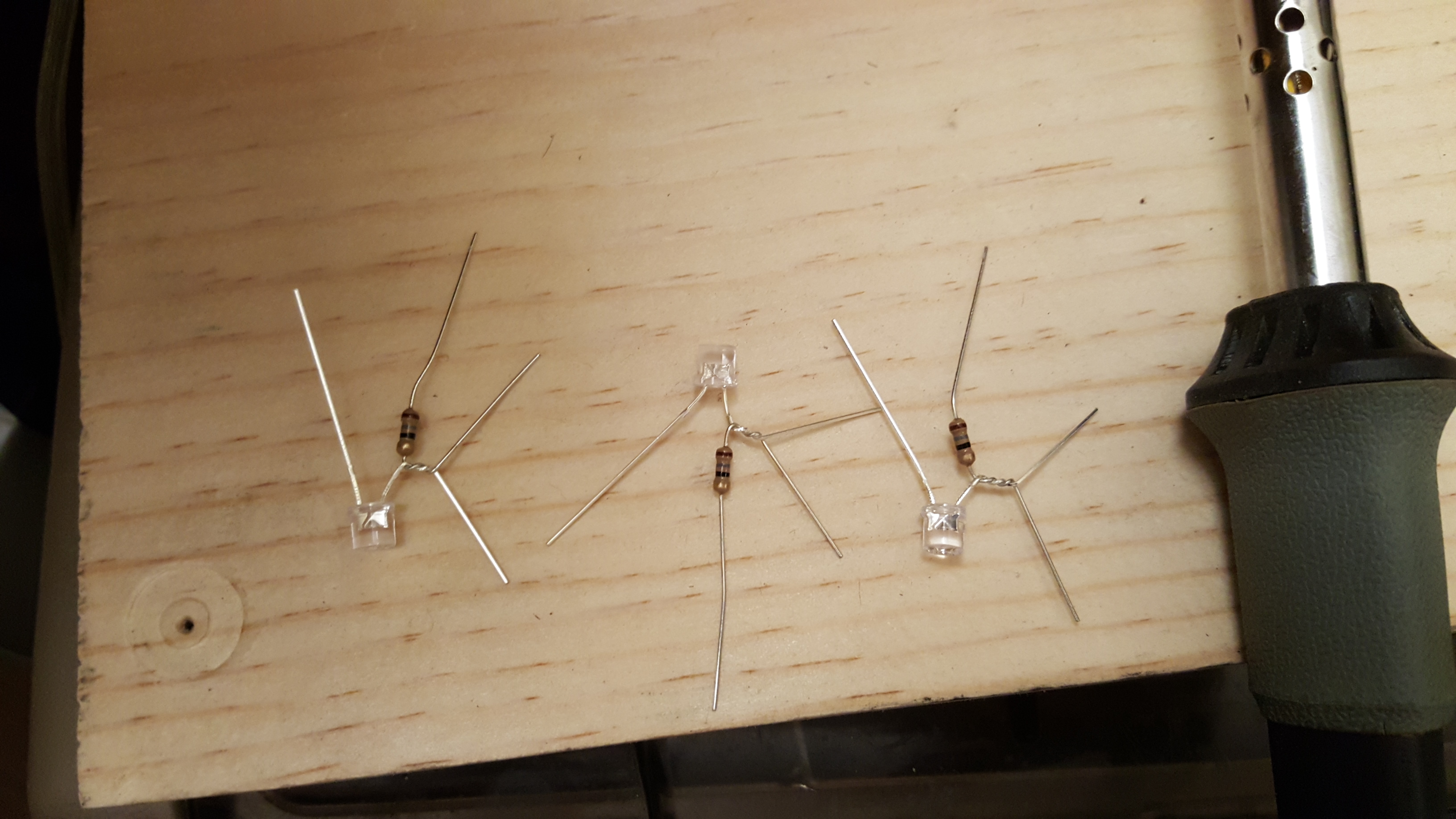
The led assembly was bent and trimmed according to a template so that it would mate with the spade terminals at the right angles inside the center piece.
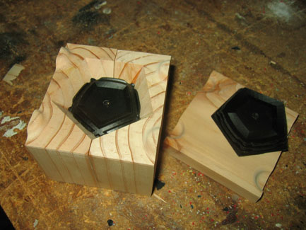
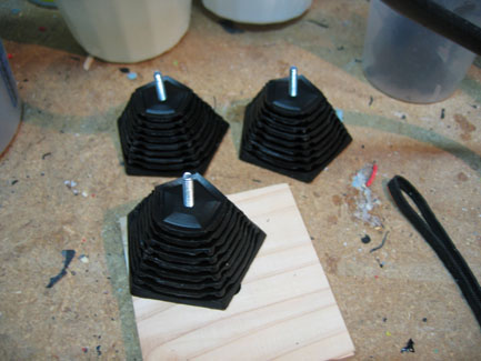
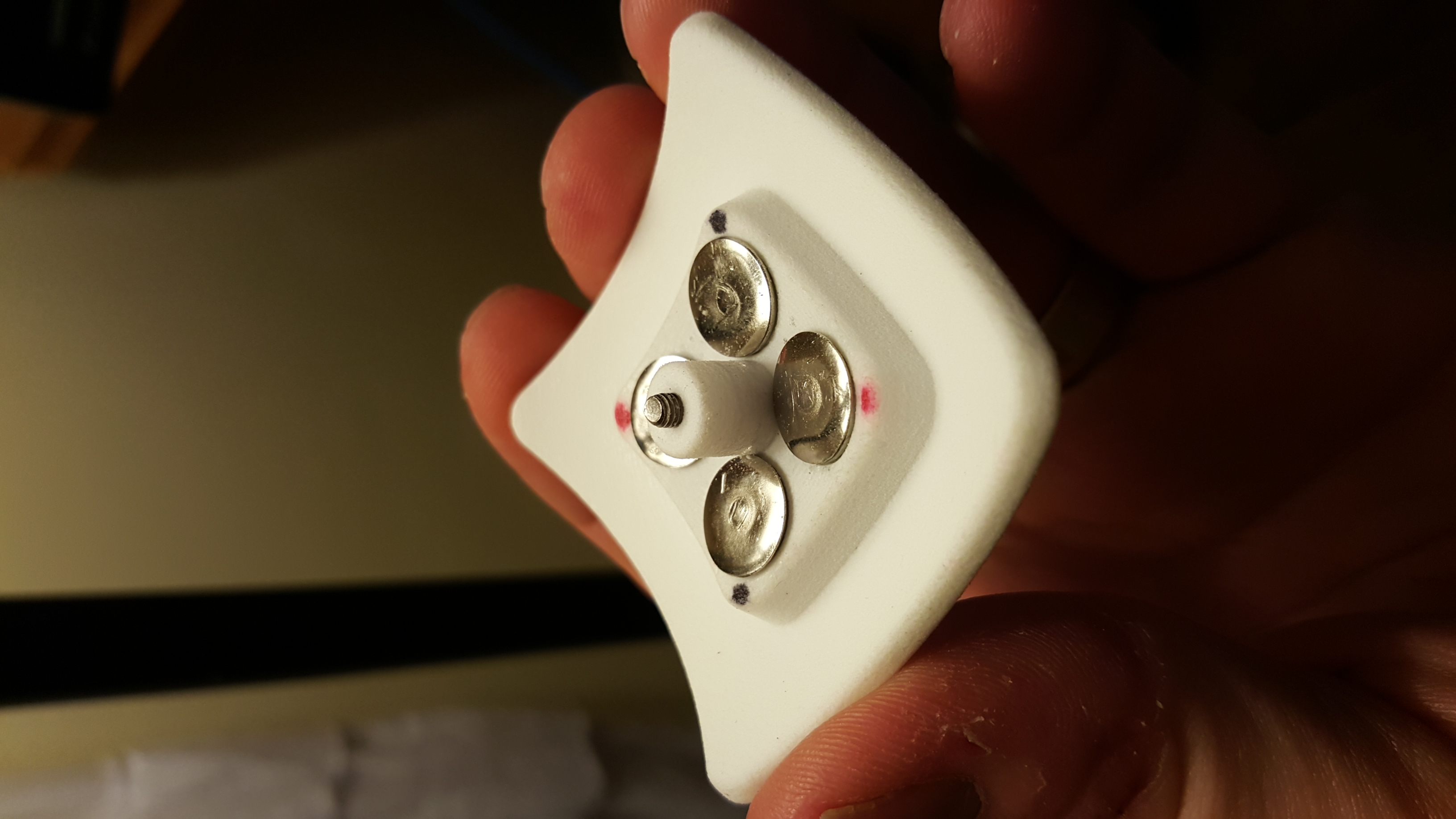
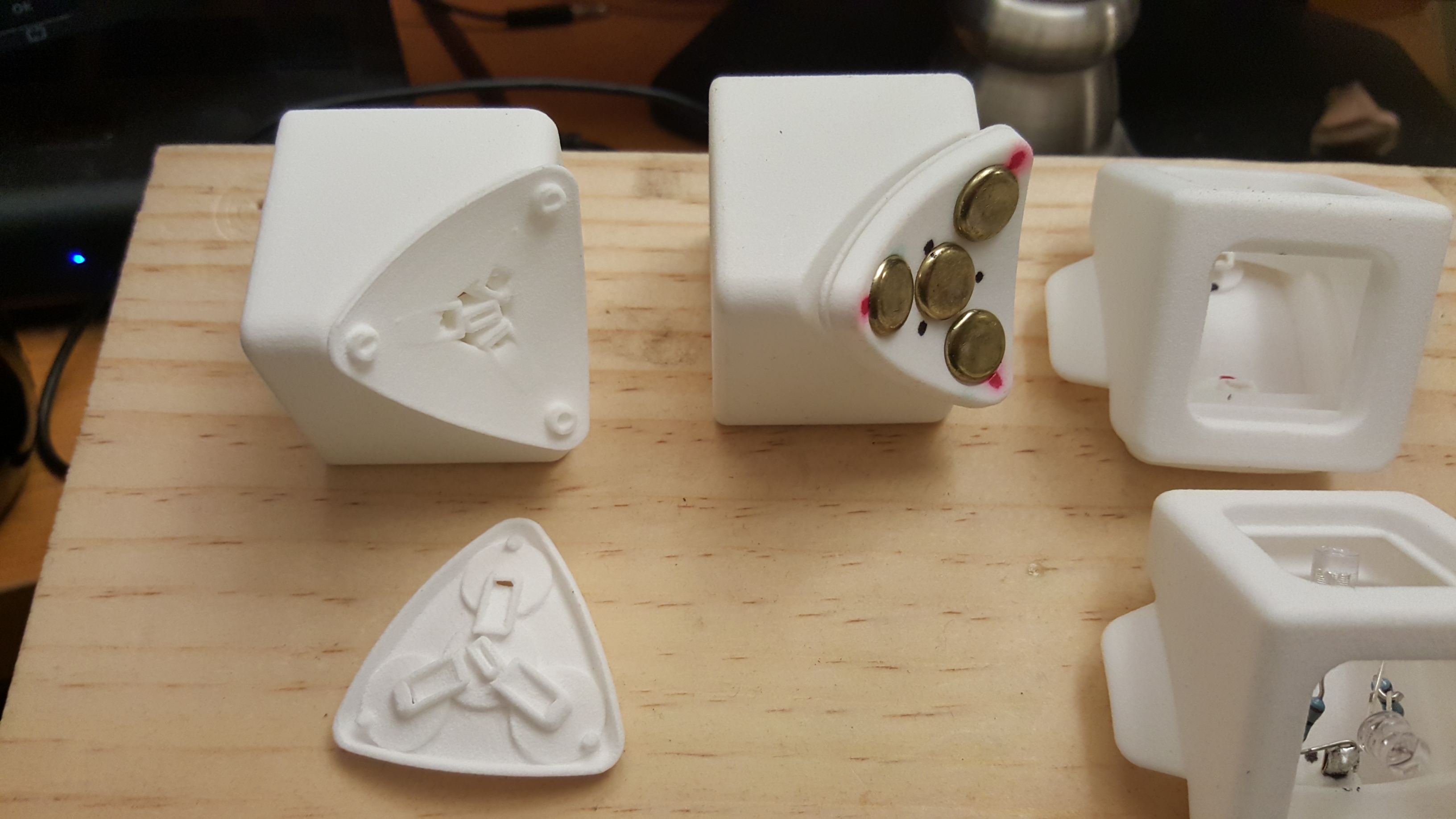
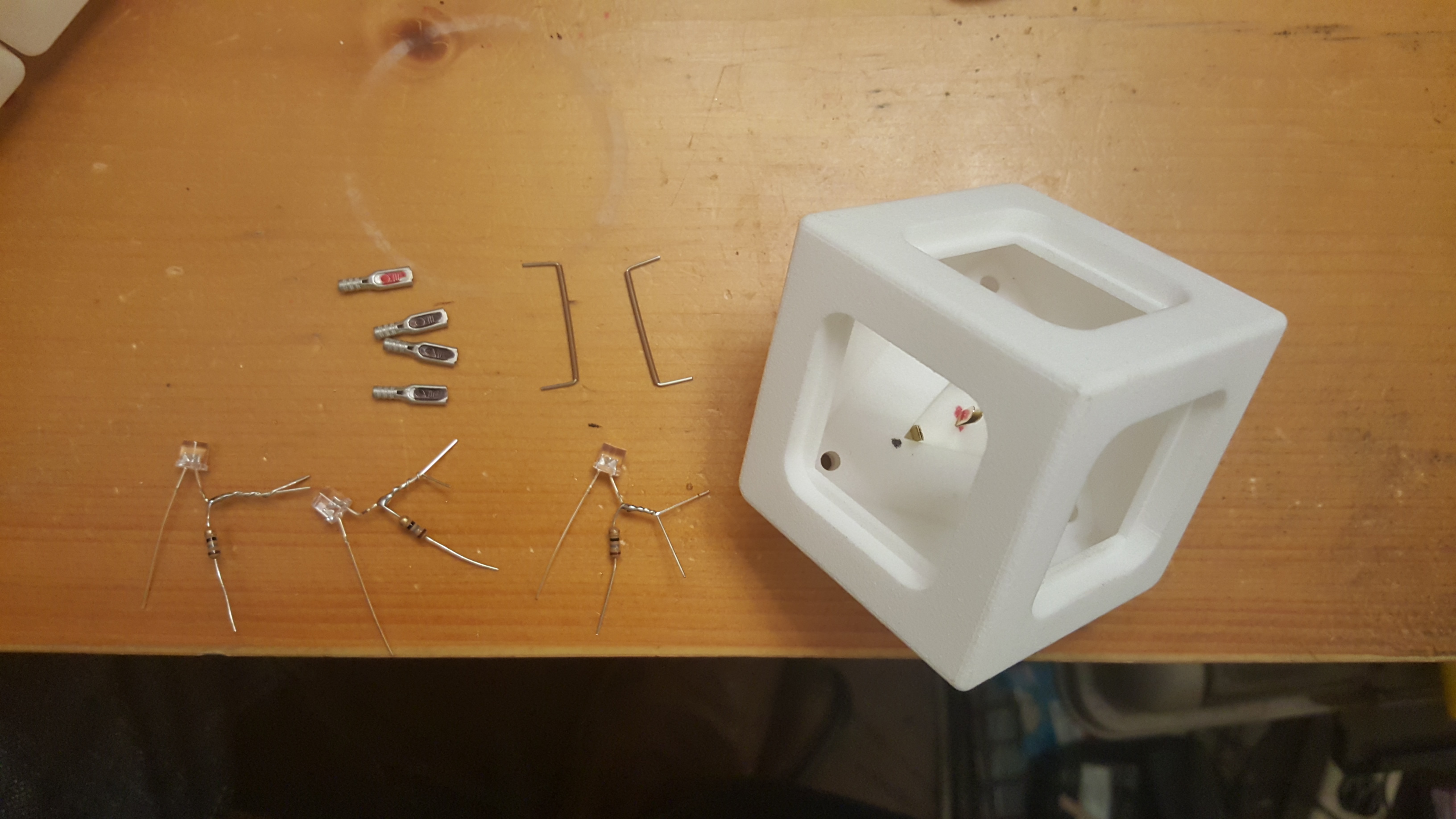
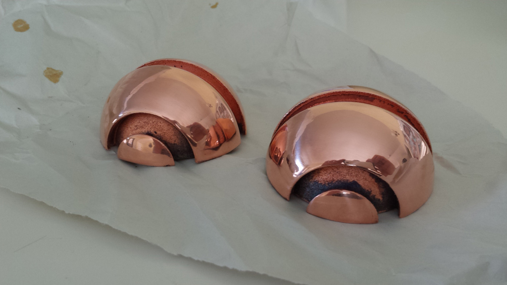
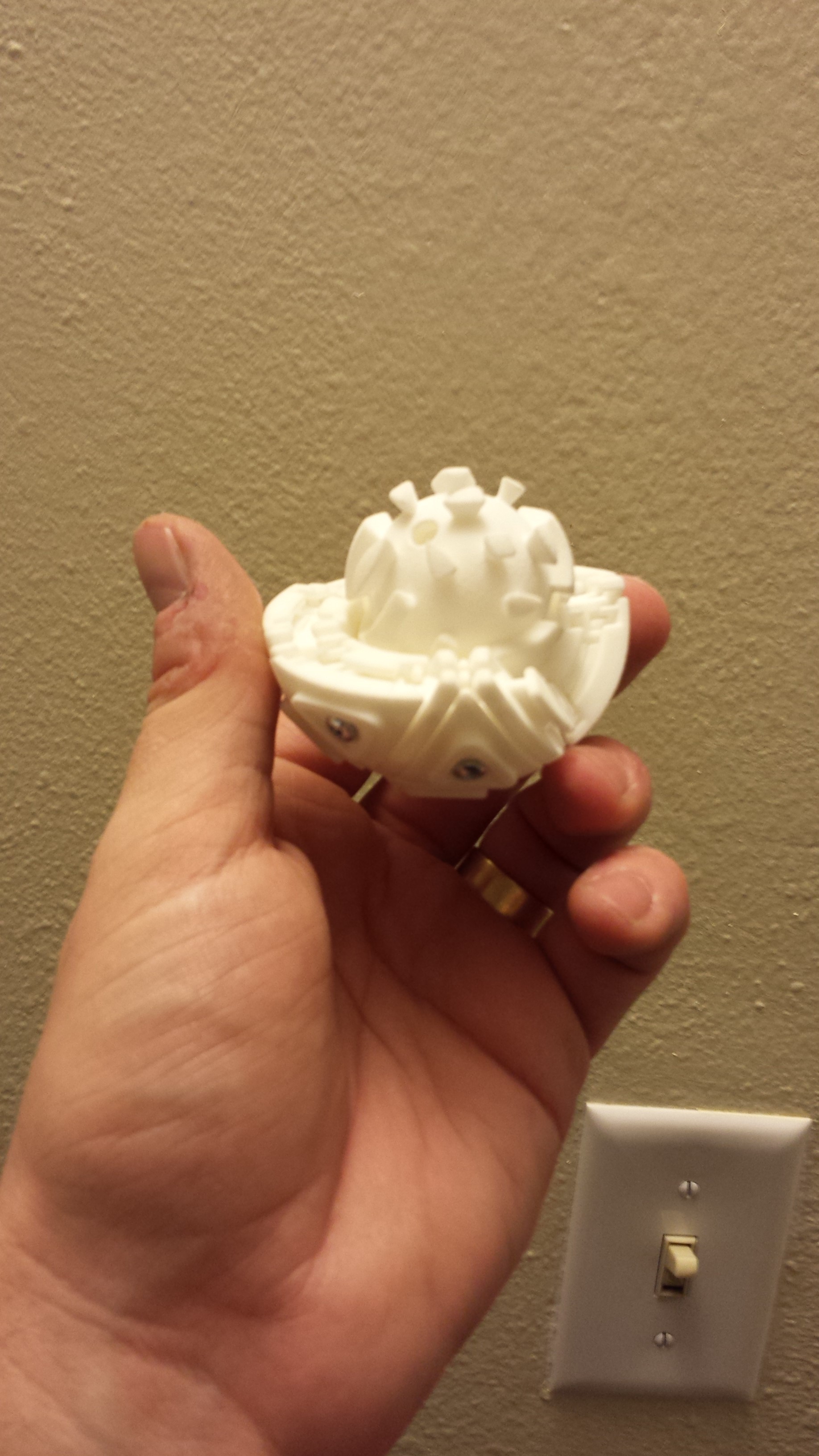
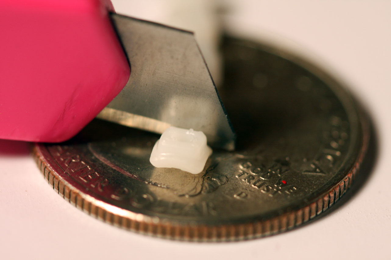
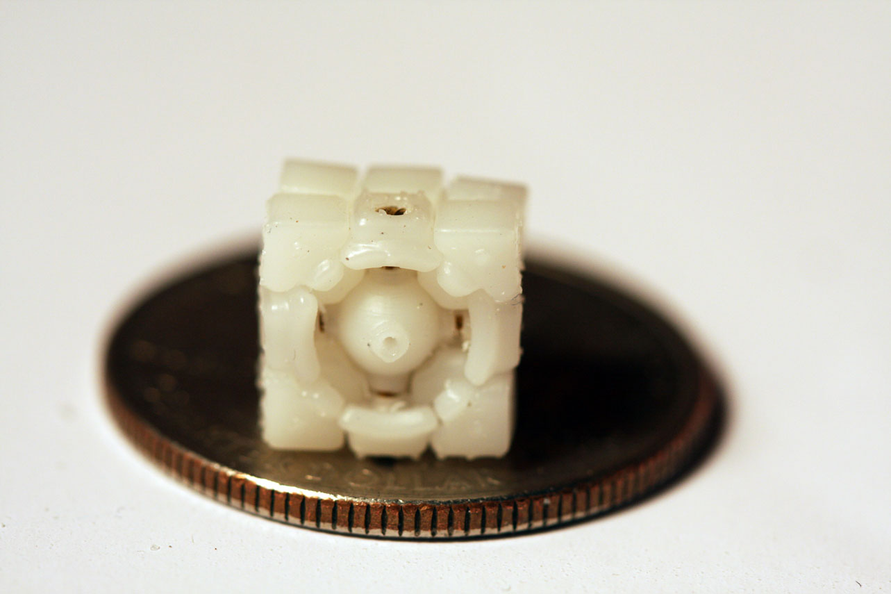
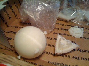
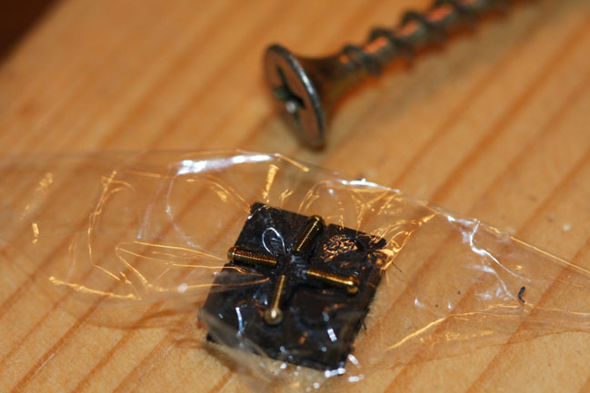
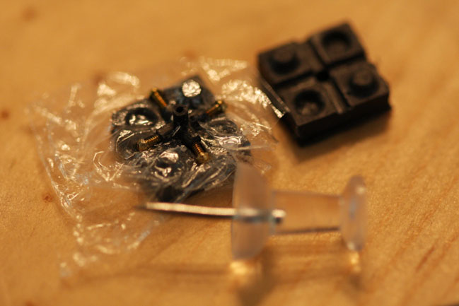
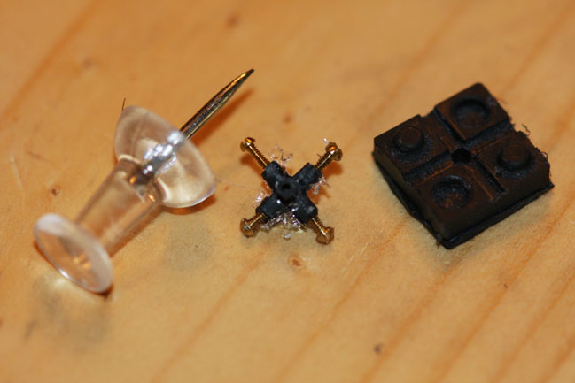
Here are the parts needed. The 3D printed center. The 3D printed reflector, which doesn’t really reflect. It just covers the electronics and allows the LED to show through. Four spade terminals. Two wires. Four brads with ring magnets applied.
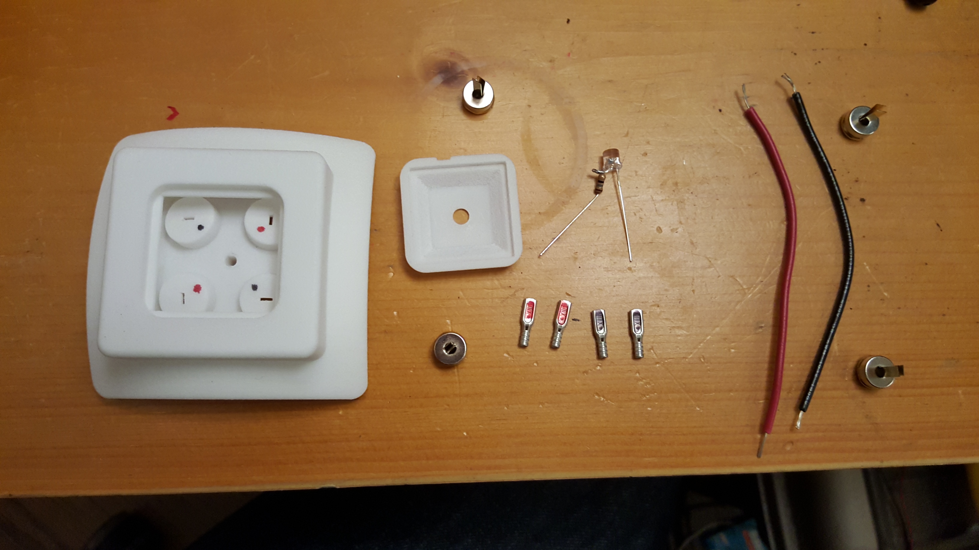
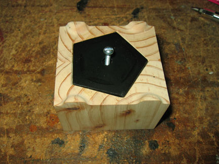
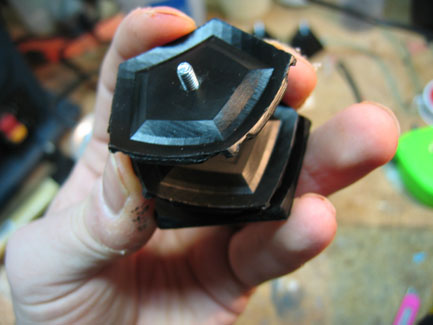
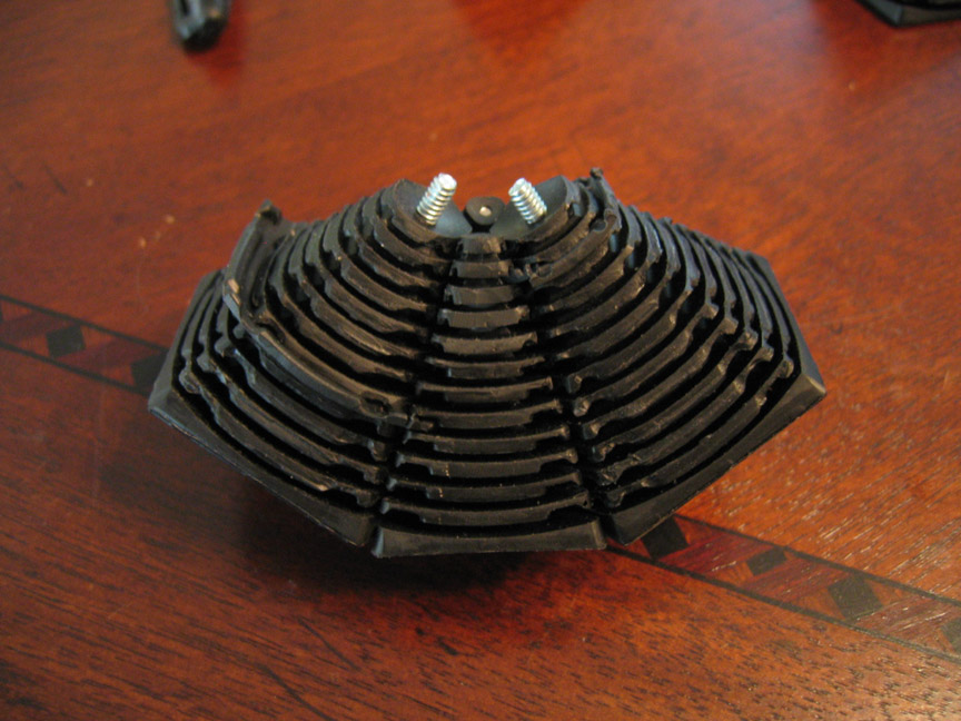
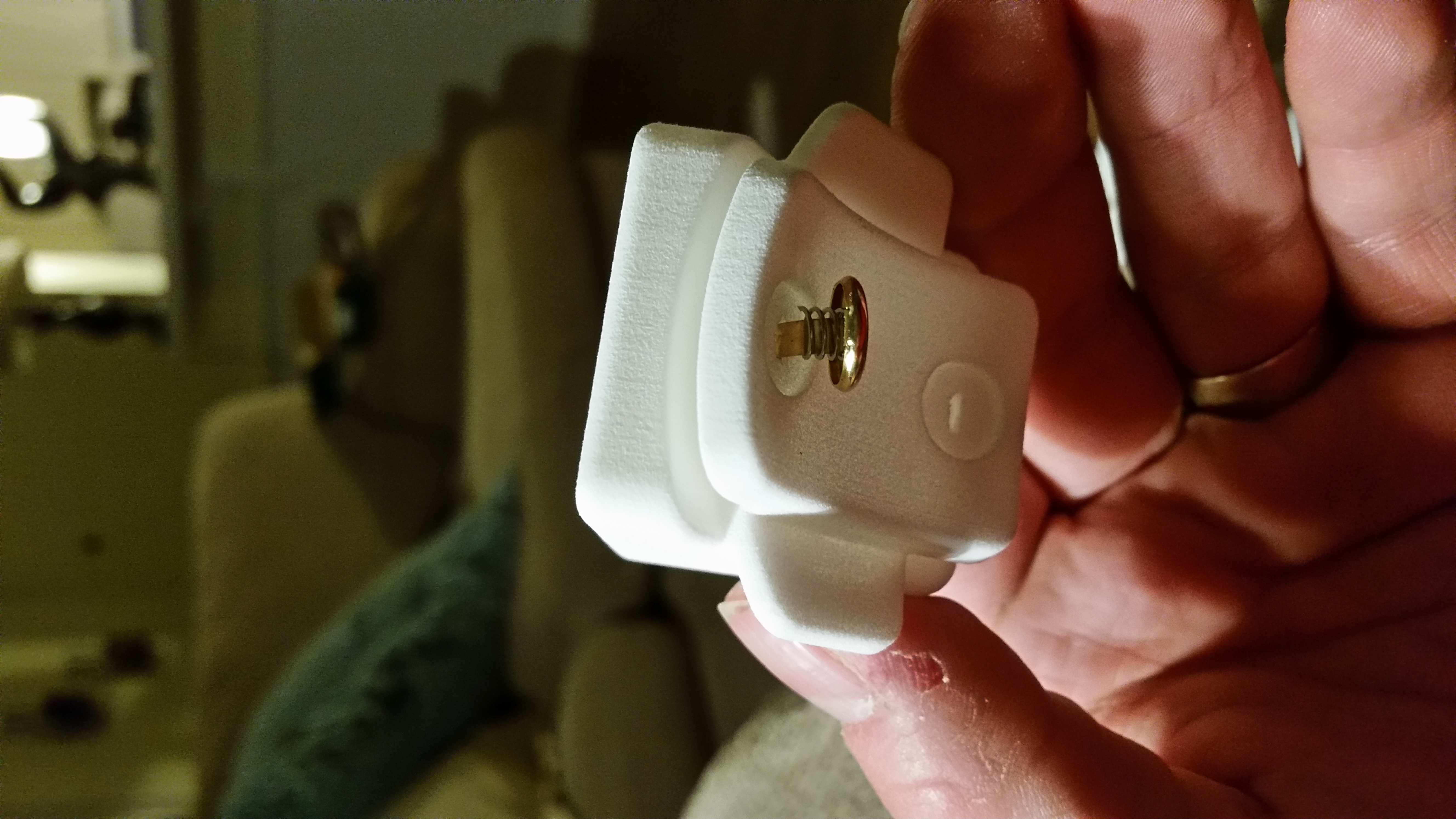
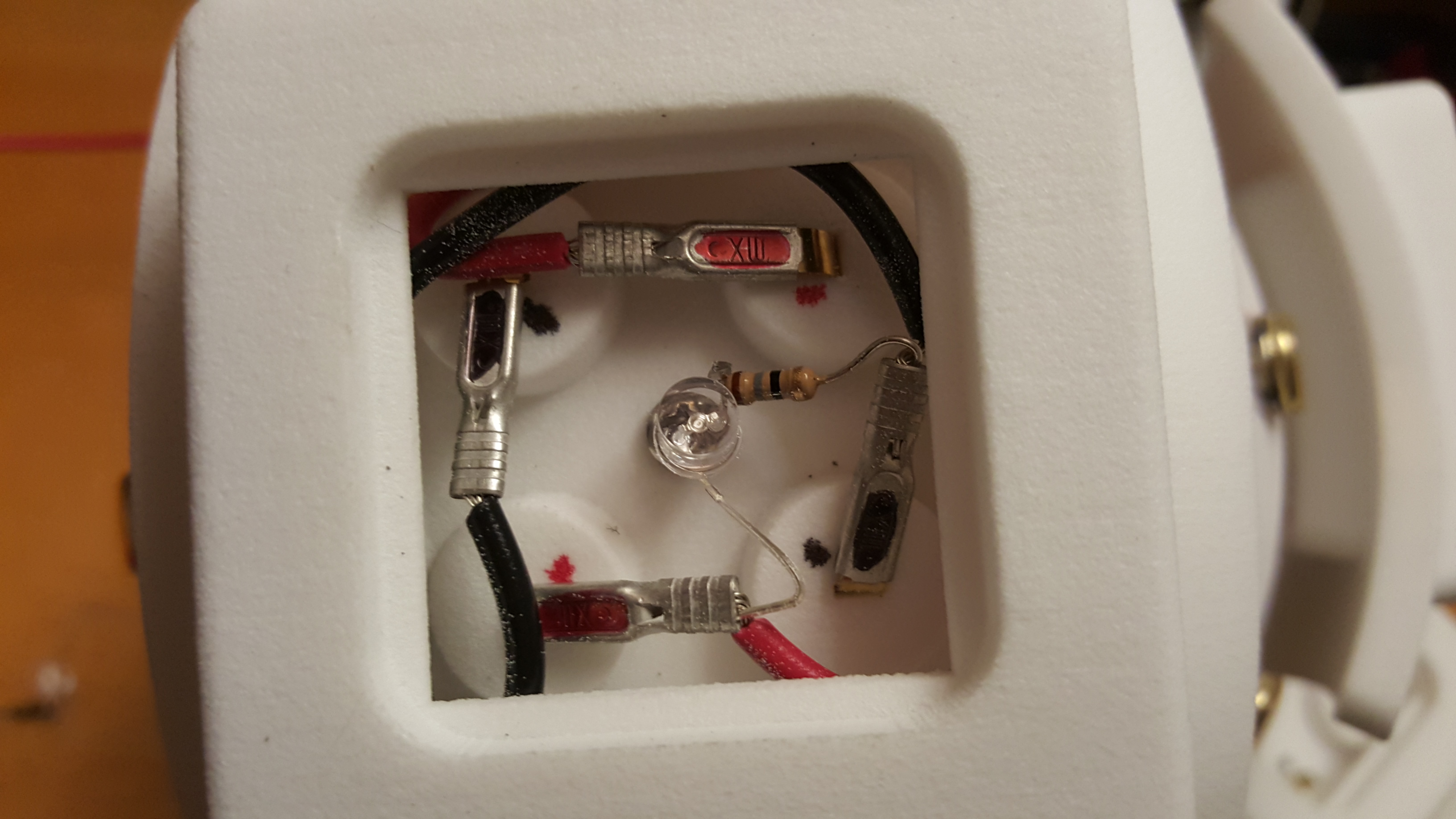
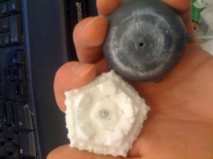
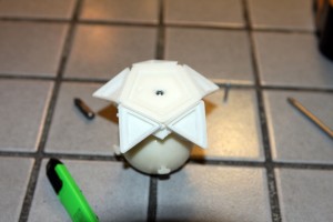
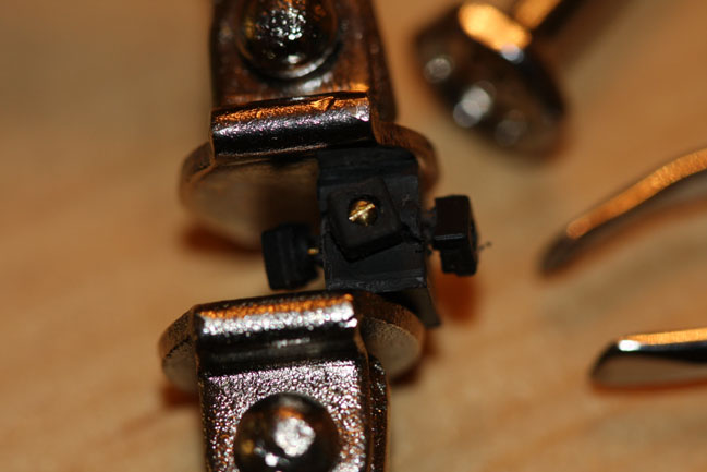
And here is the completed center. The screw is reached by gently pushing the LED aside.
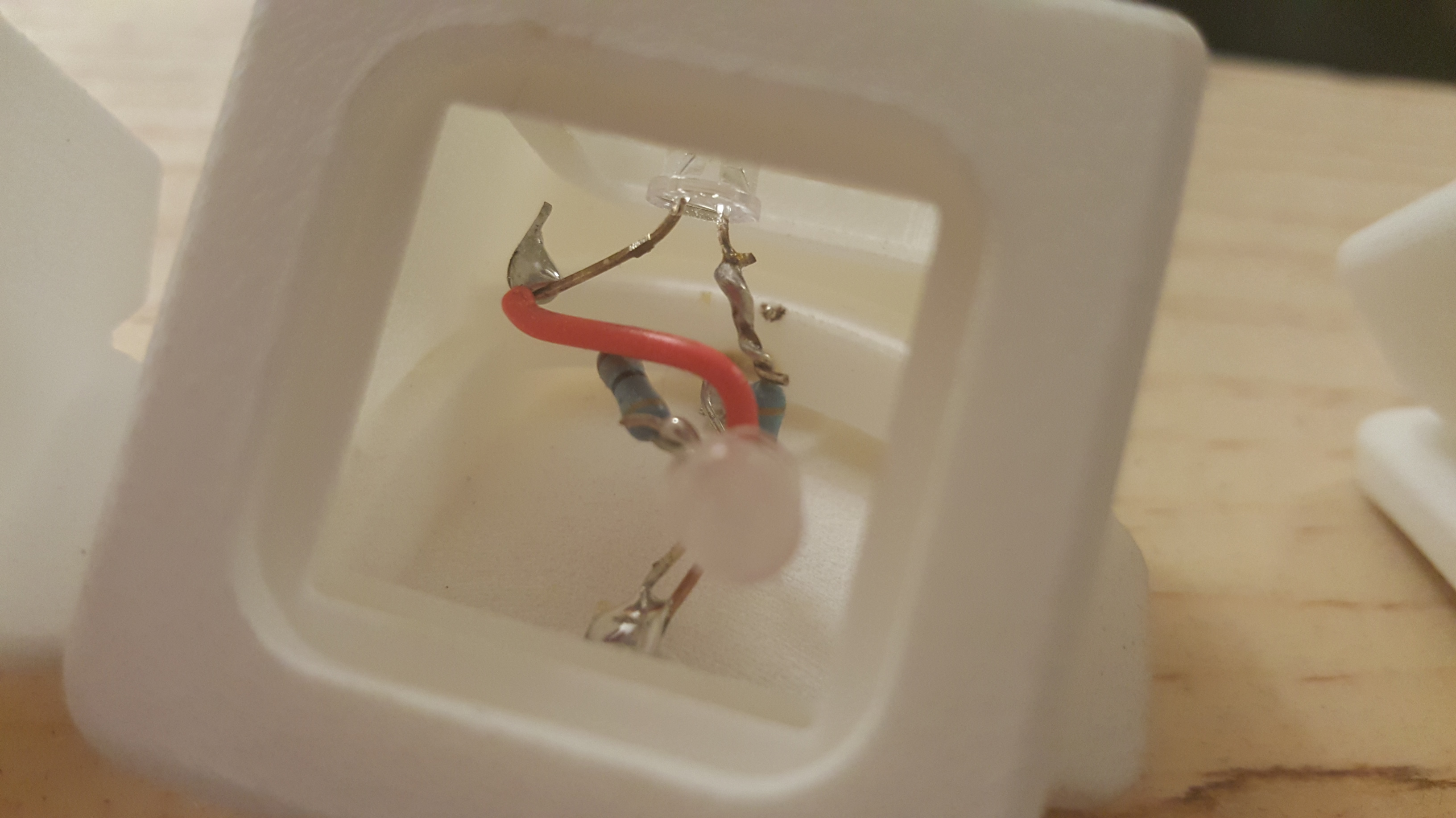
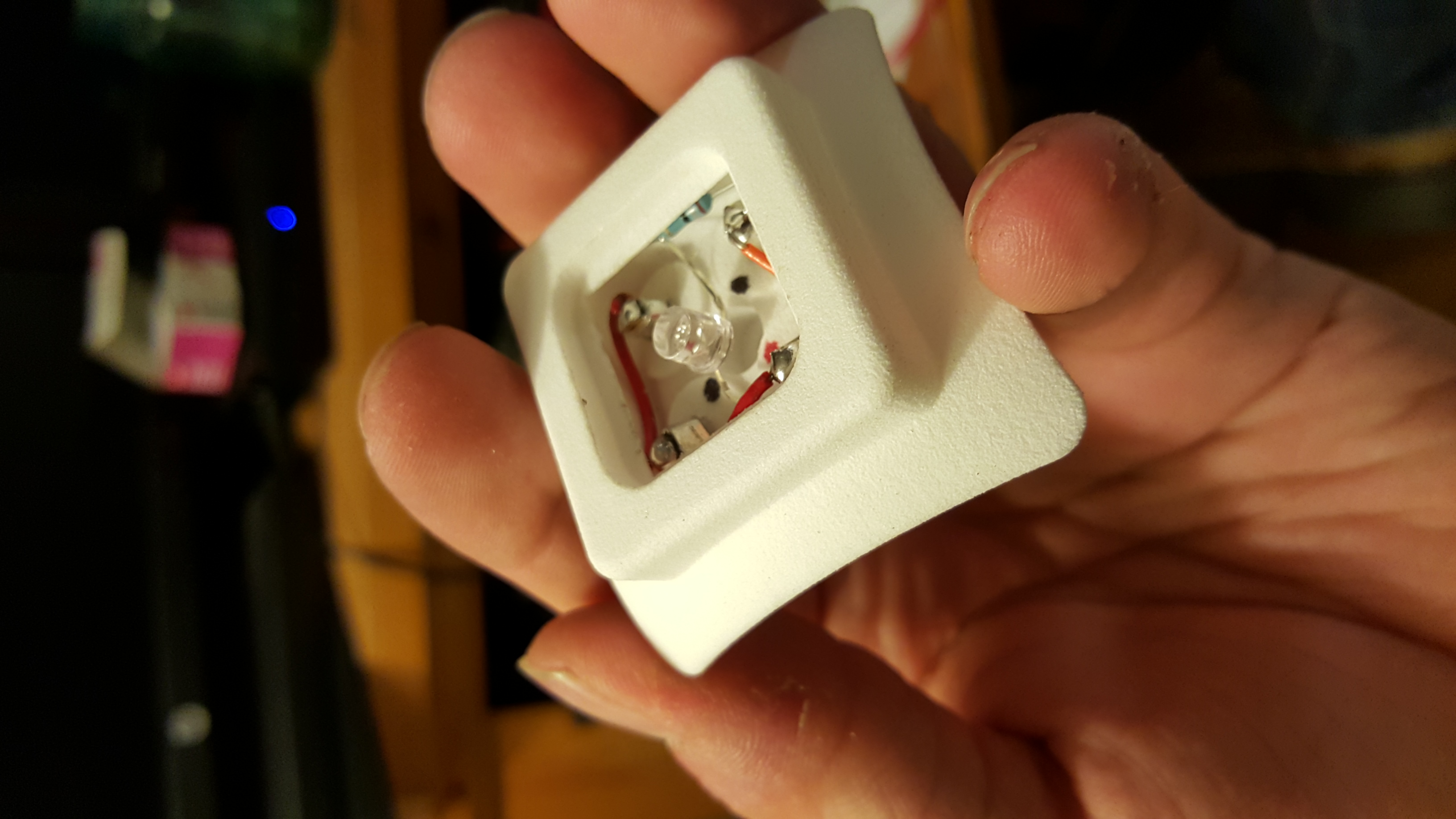
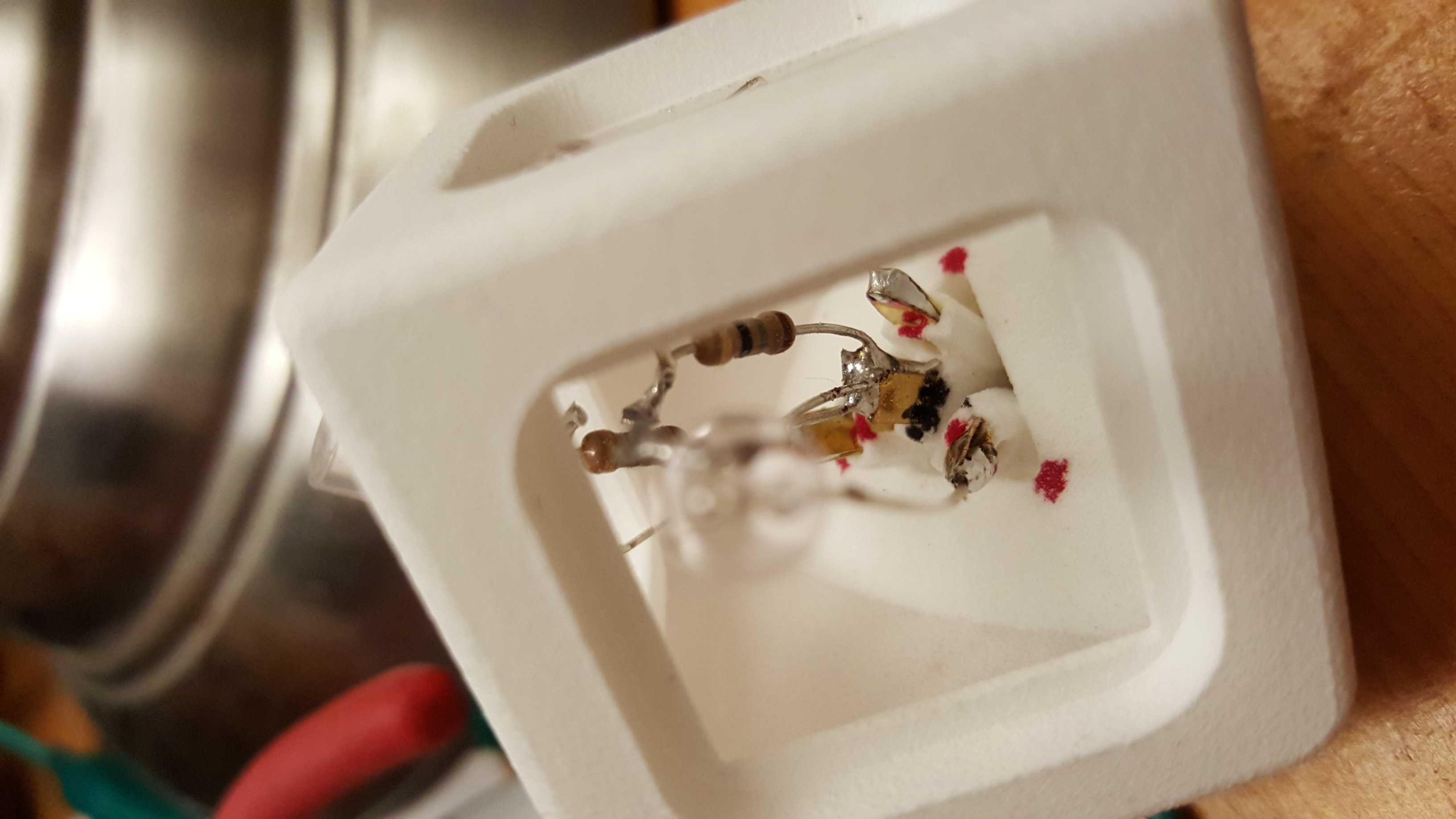
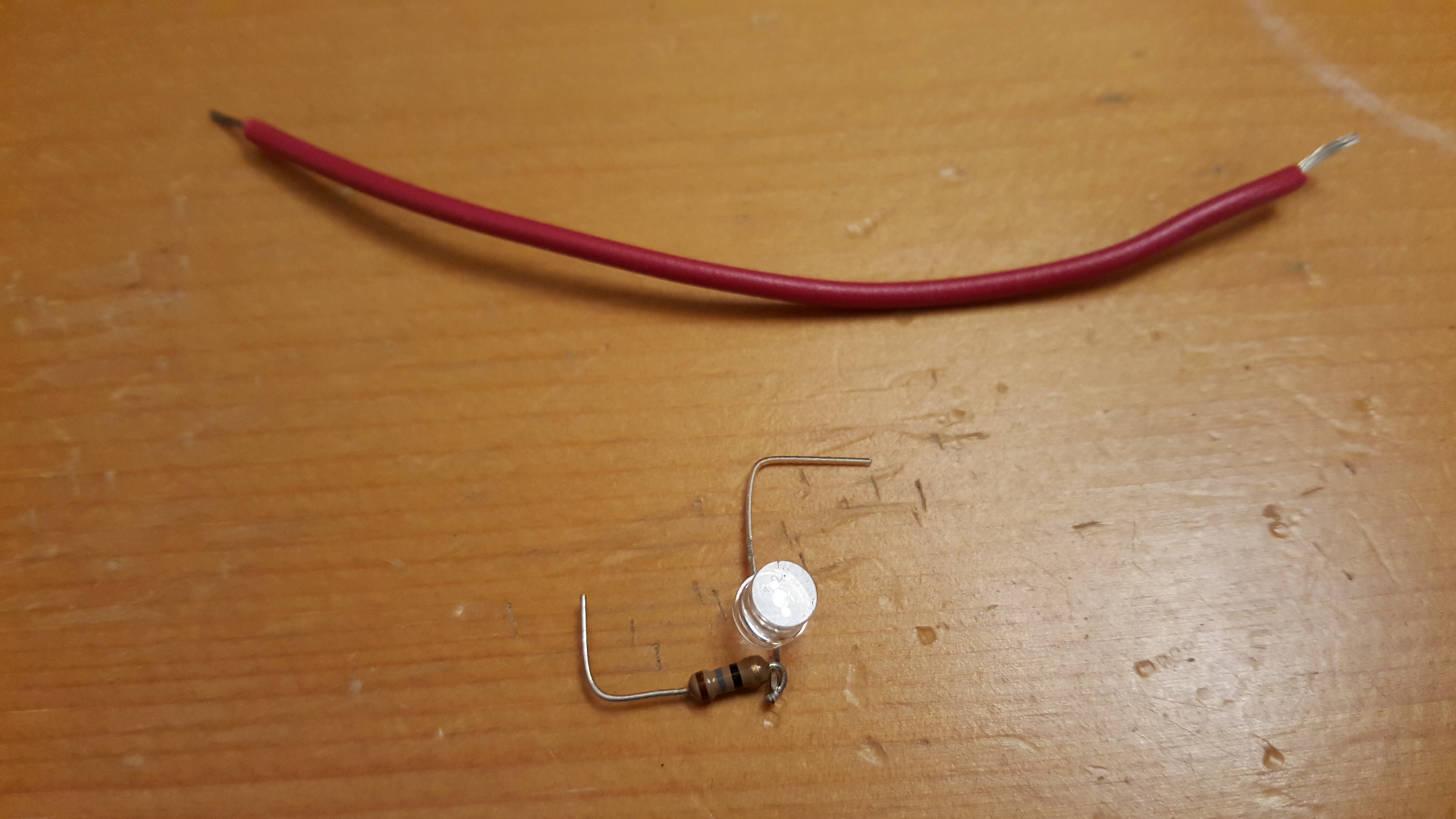
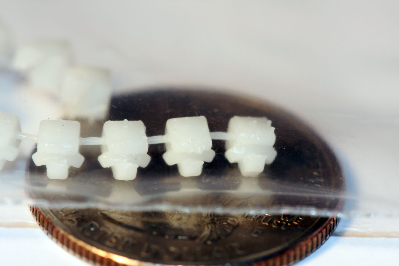
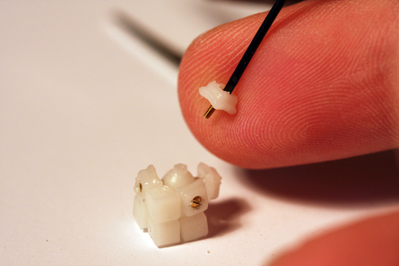
Edges were done in a similar way. Parts were prepared, including an LED harness with two LEDs, two resistors and two spade connectors. And two brads with magnets applied. In this photo you can see how the brad legs can now just enter the bottom of the 3D printed edge and come straight into the part.
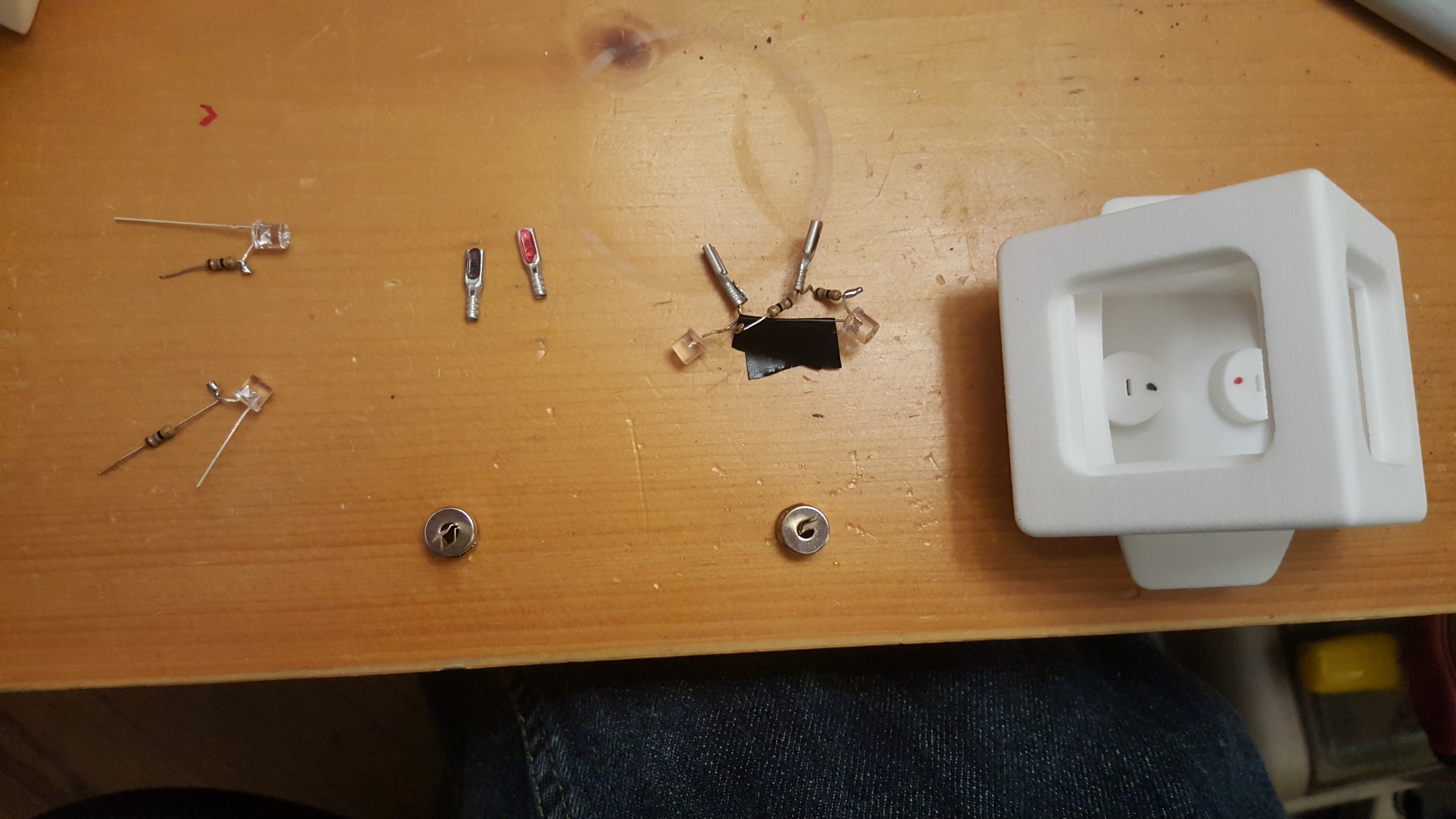
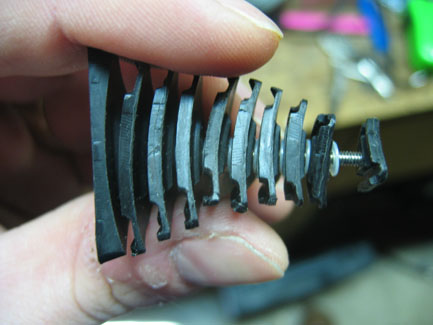
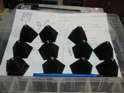
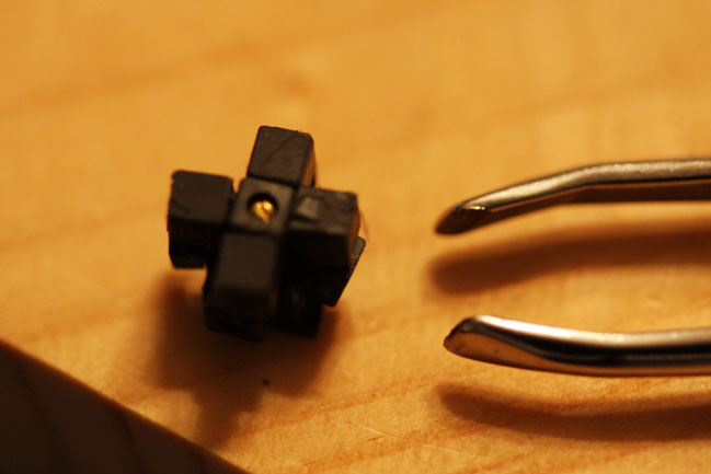
A few edges were assembled in succession.
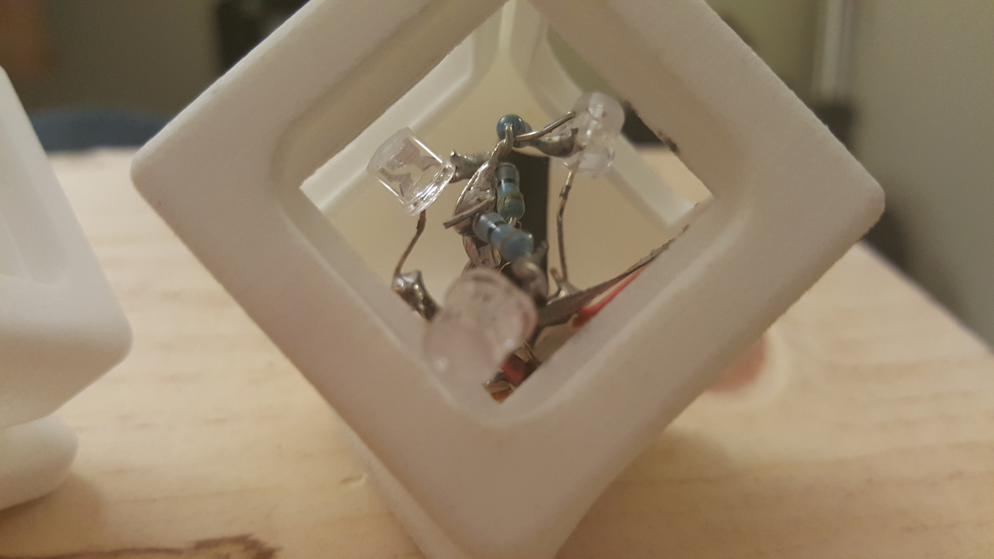
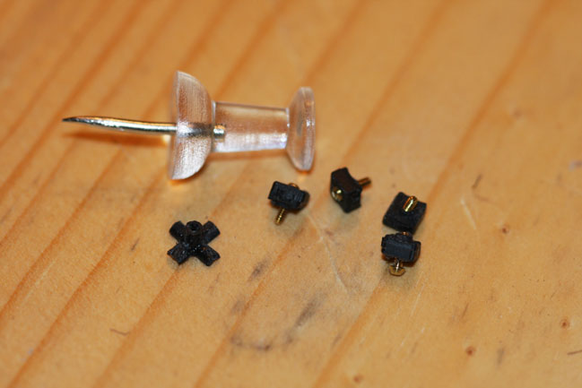
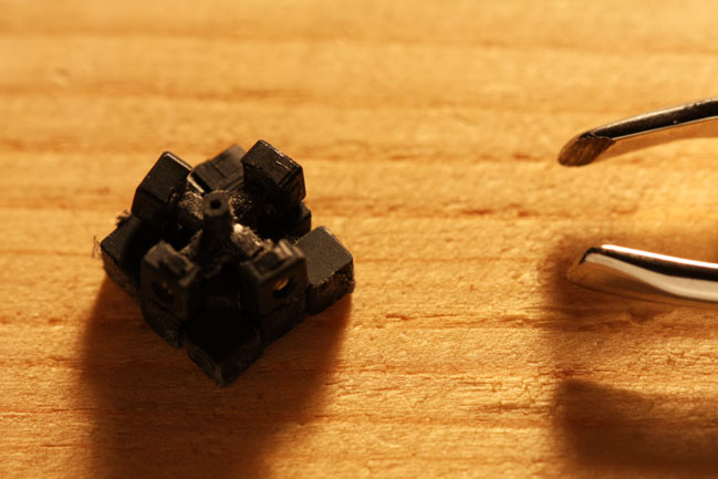
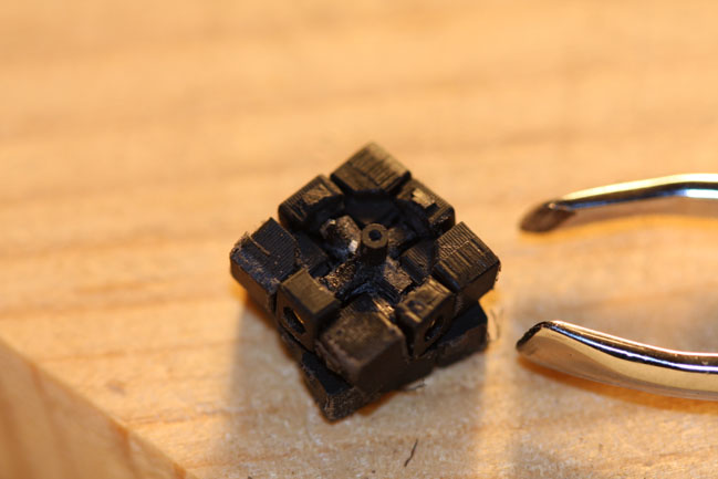
Corners require 4 spade terminals, 3 leds, and two wires. The two wires are used to connect the outer terminals so that connection is successful even if only one makes solid contact. Assembly continued…
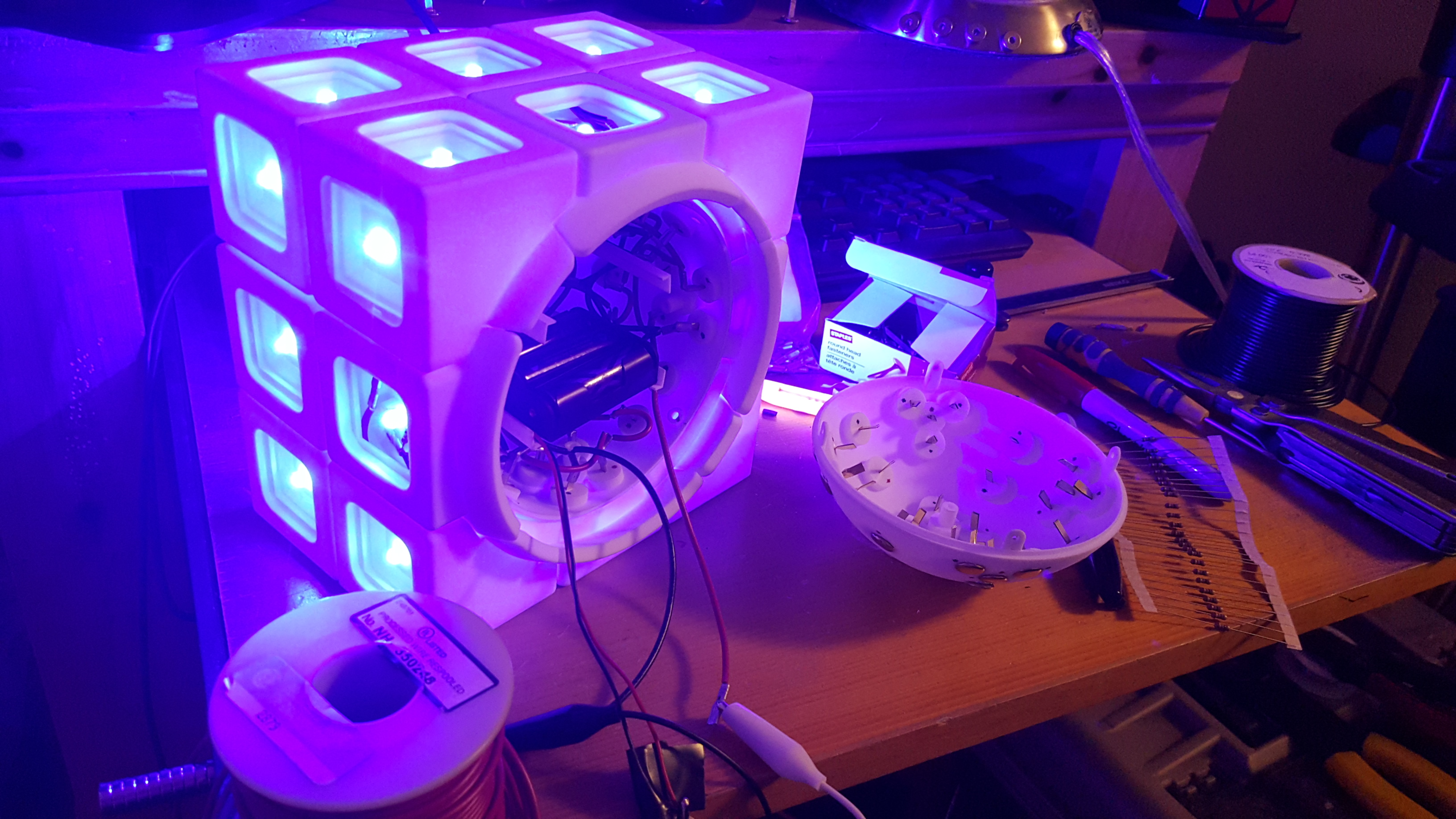
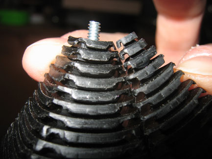
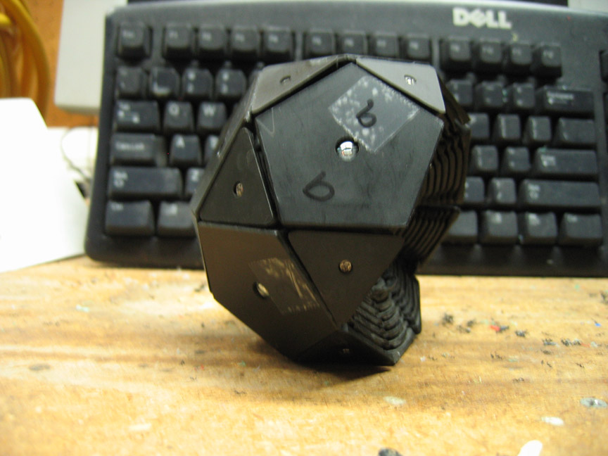
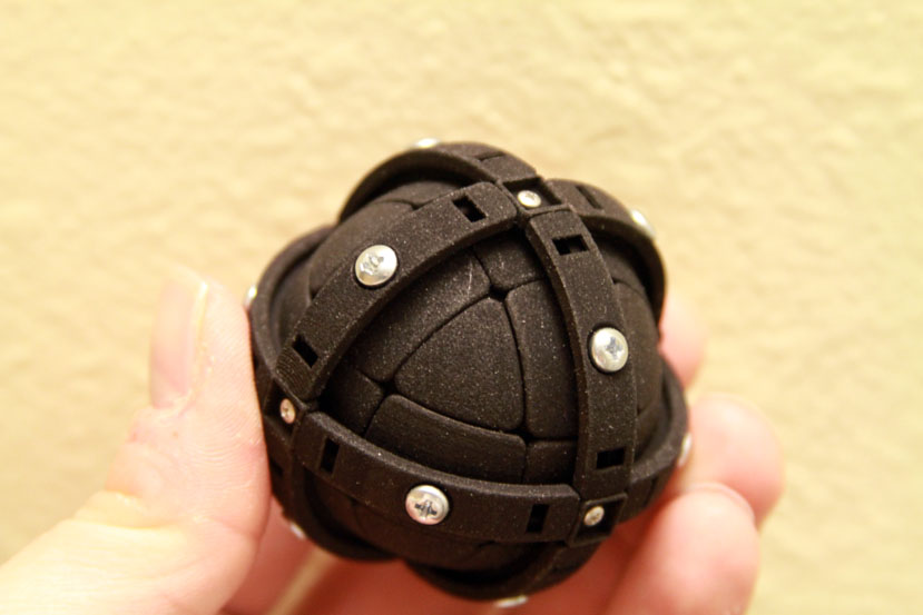
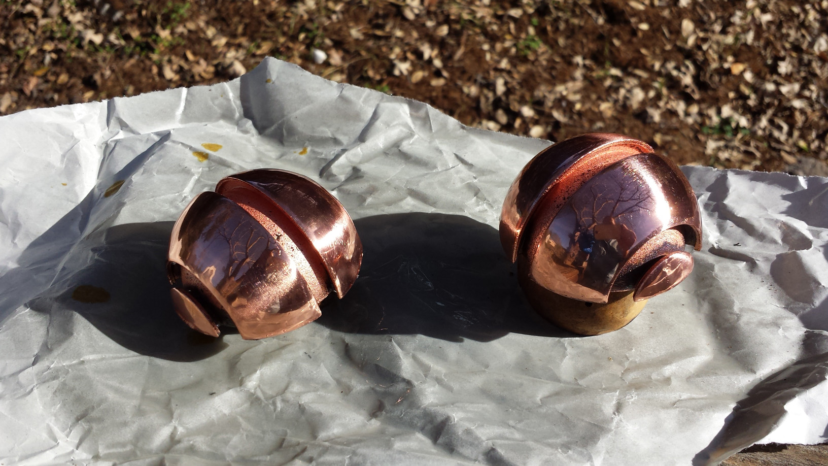
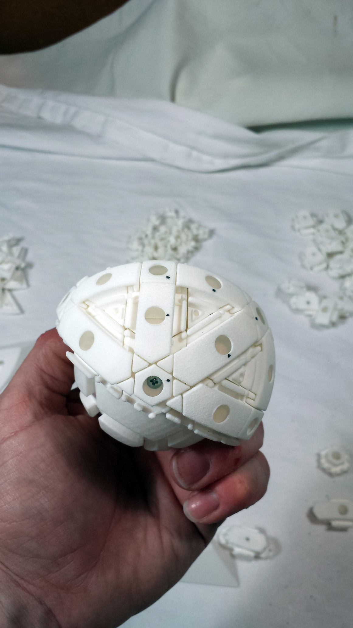
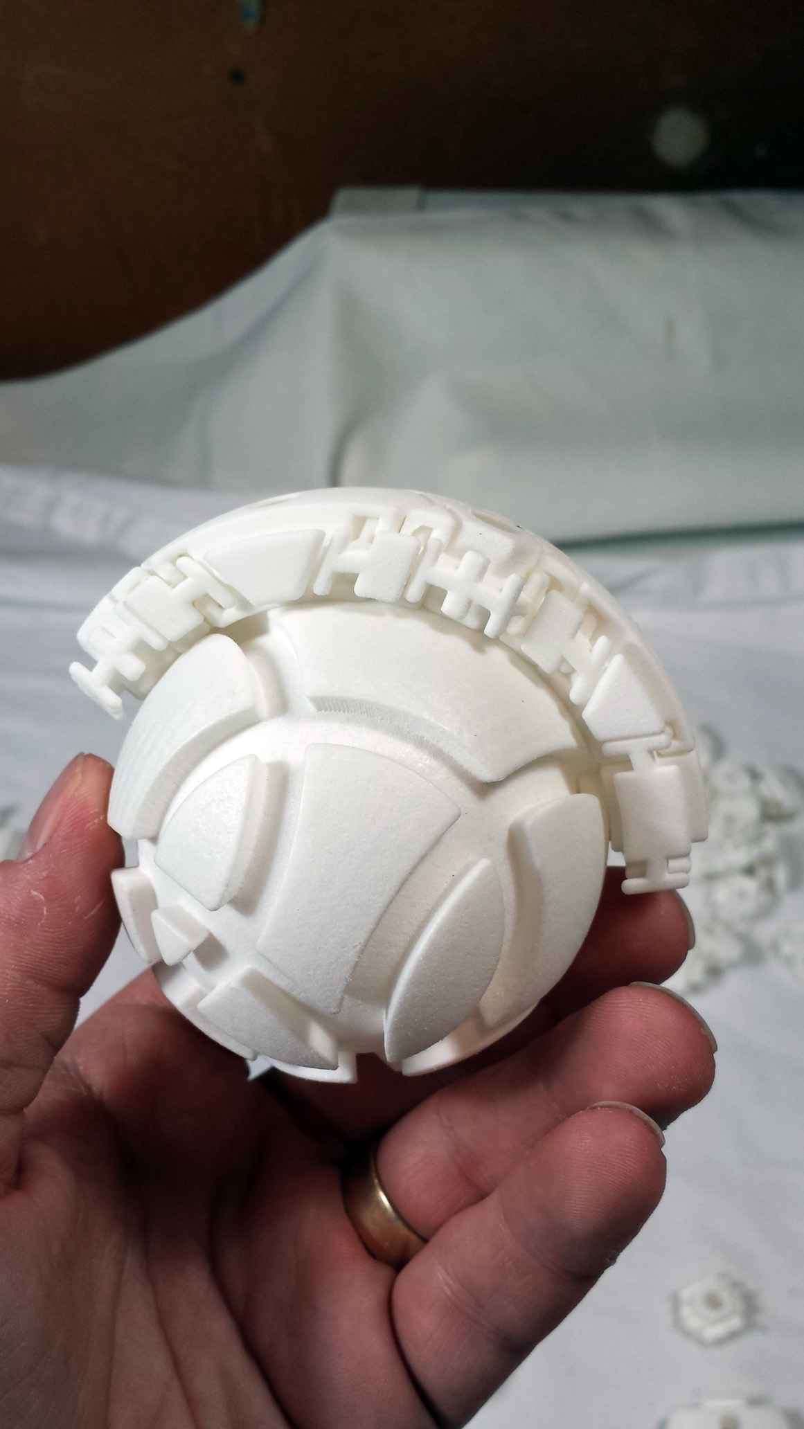
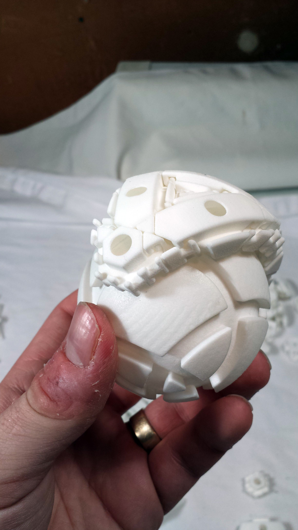
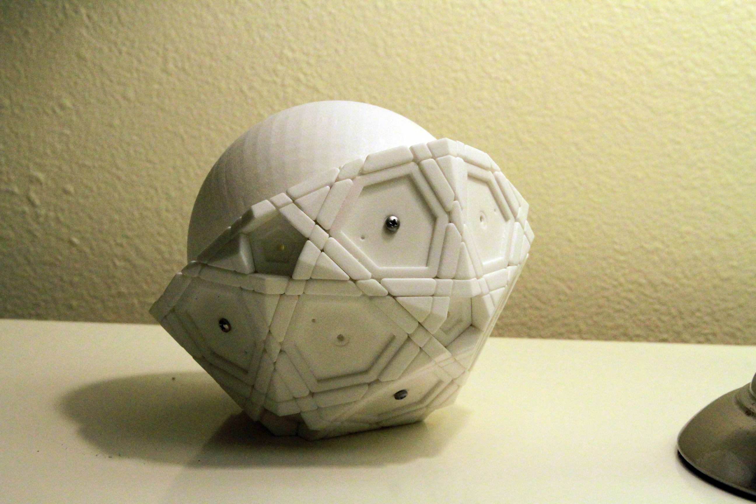
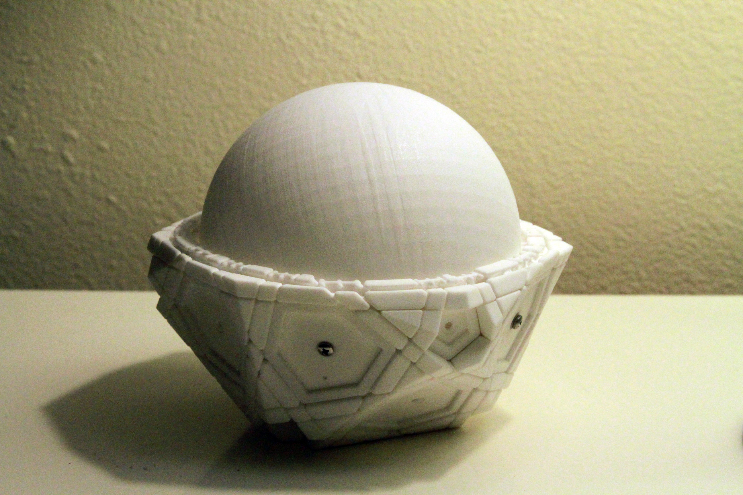
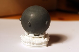
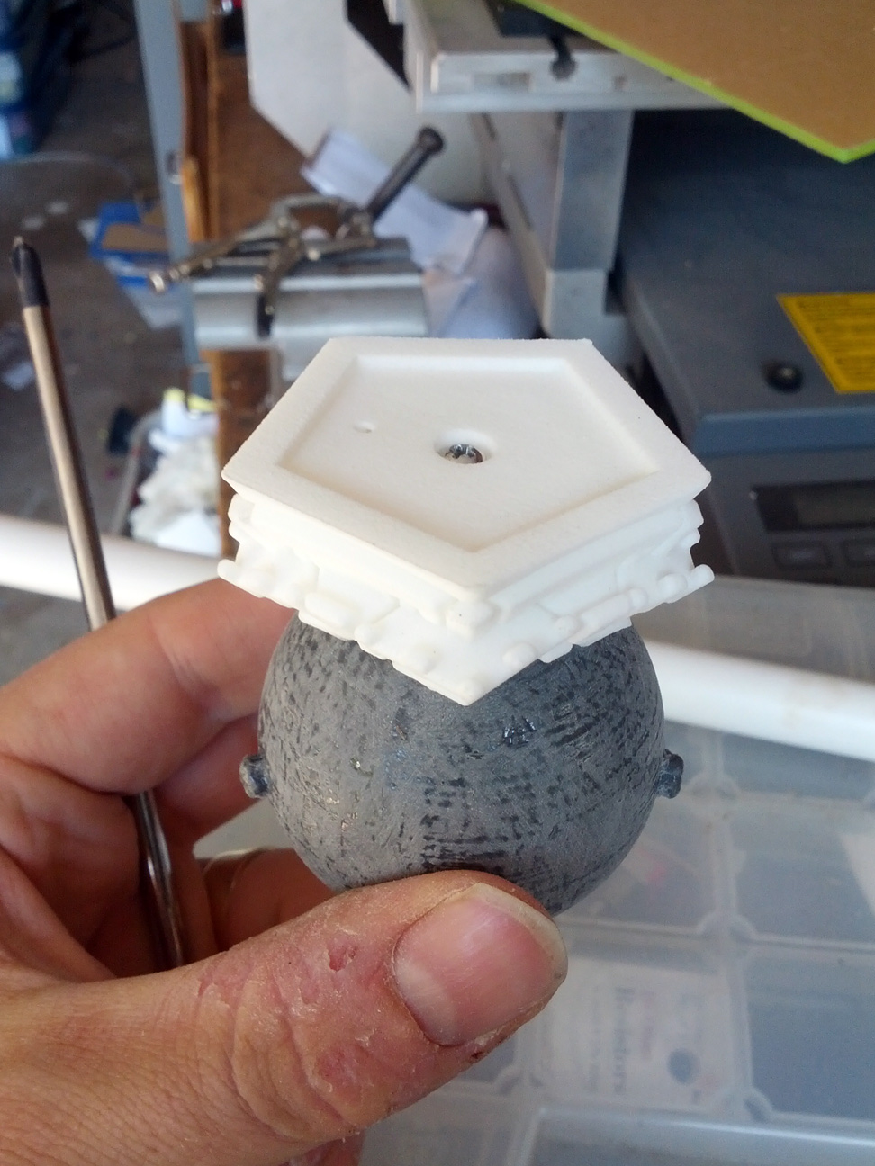
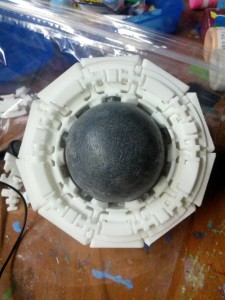
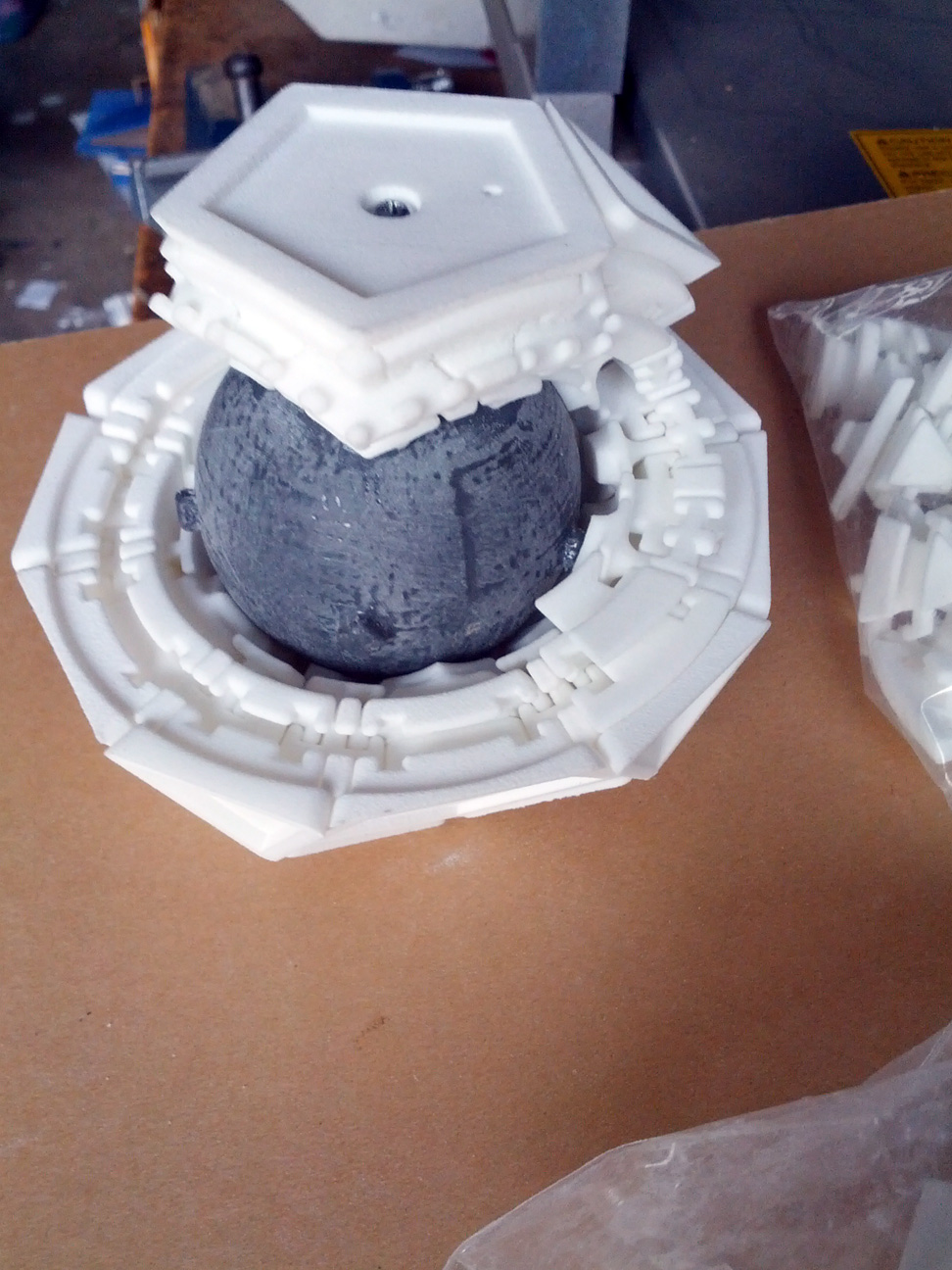
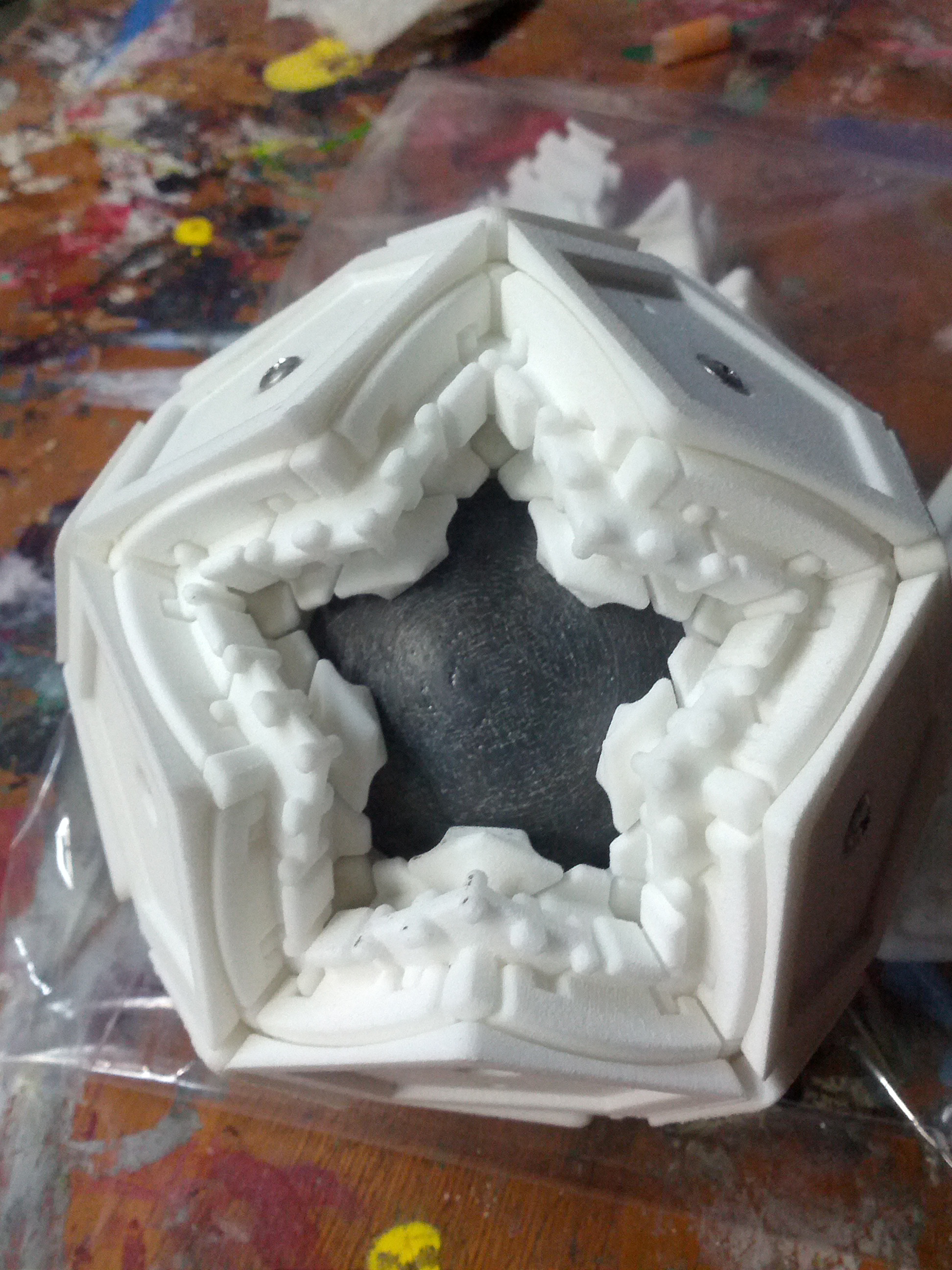
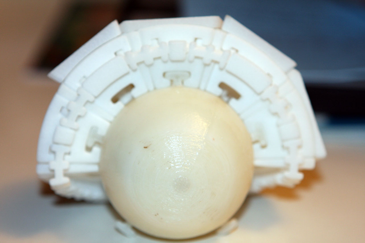
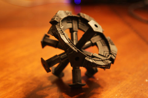
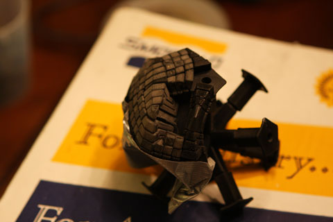
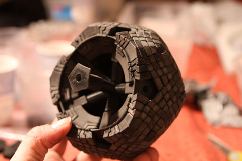
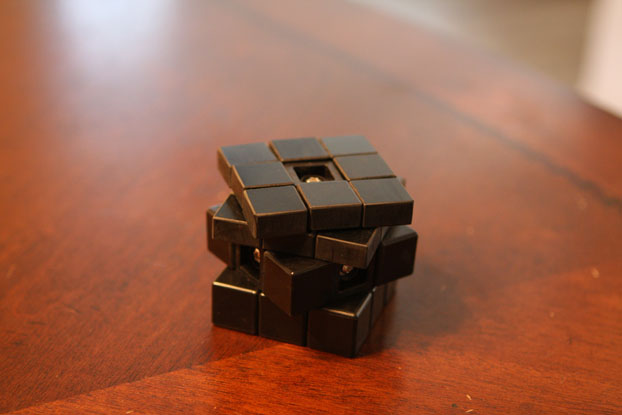
At a certain point, the puzzle was ready for the core to be closed, so the batteries were secured inside, and the core cap was applied.
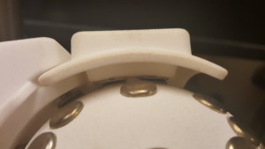
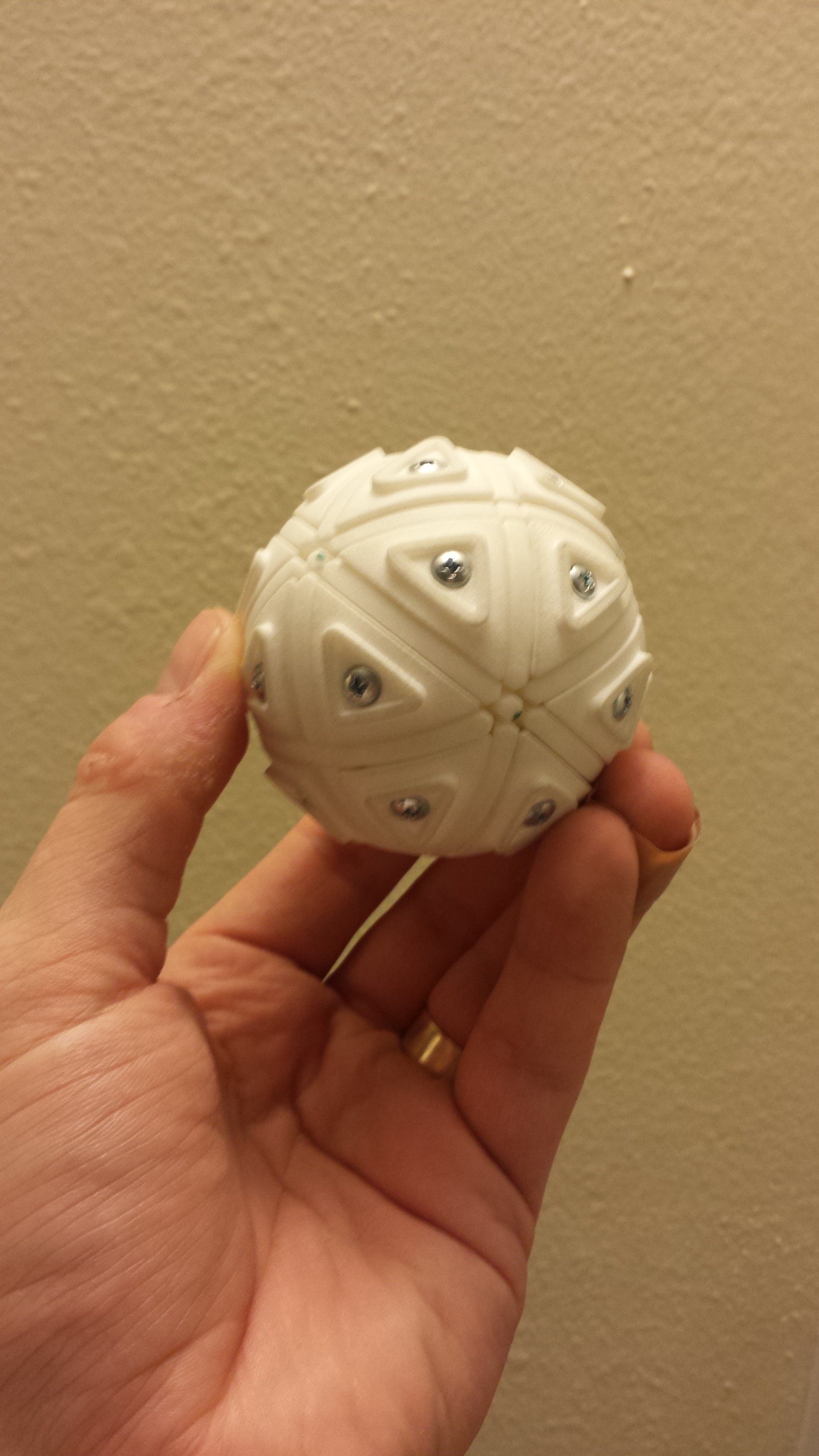
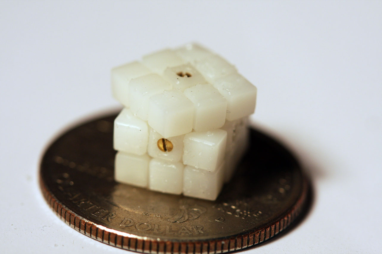
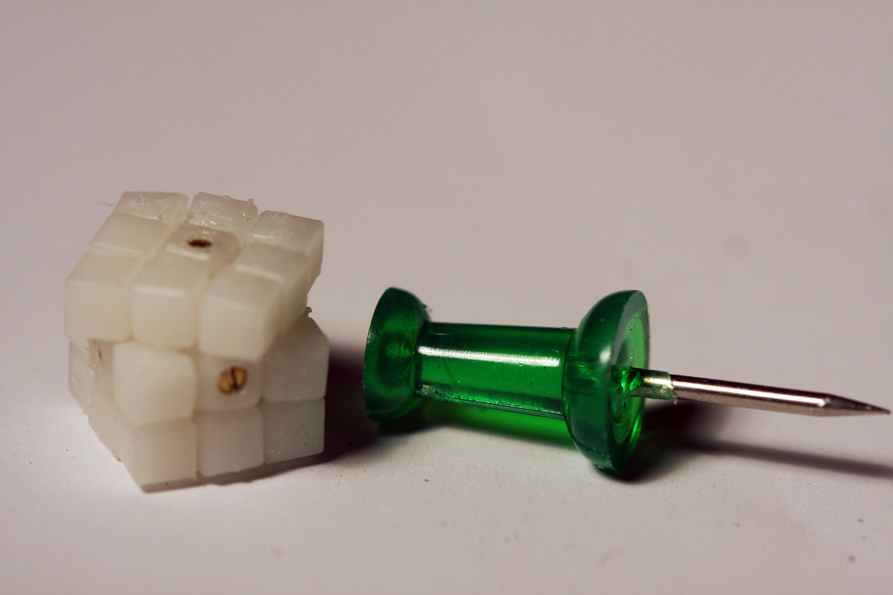
Here you can see one of four screws that secure the “halves” of the core together.
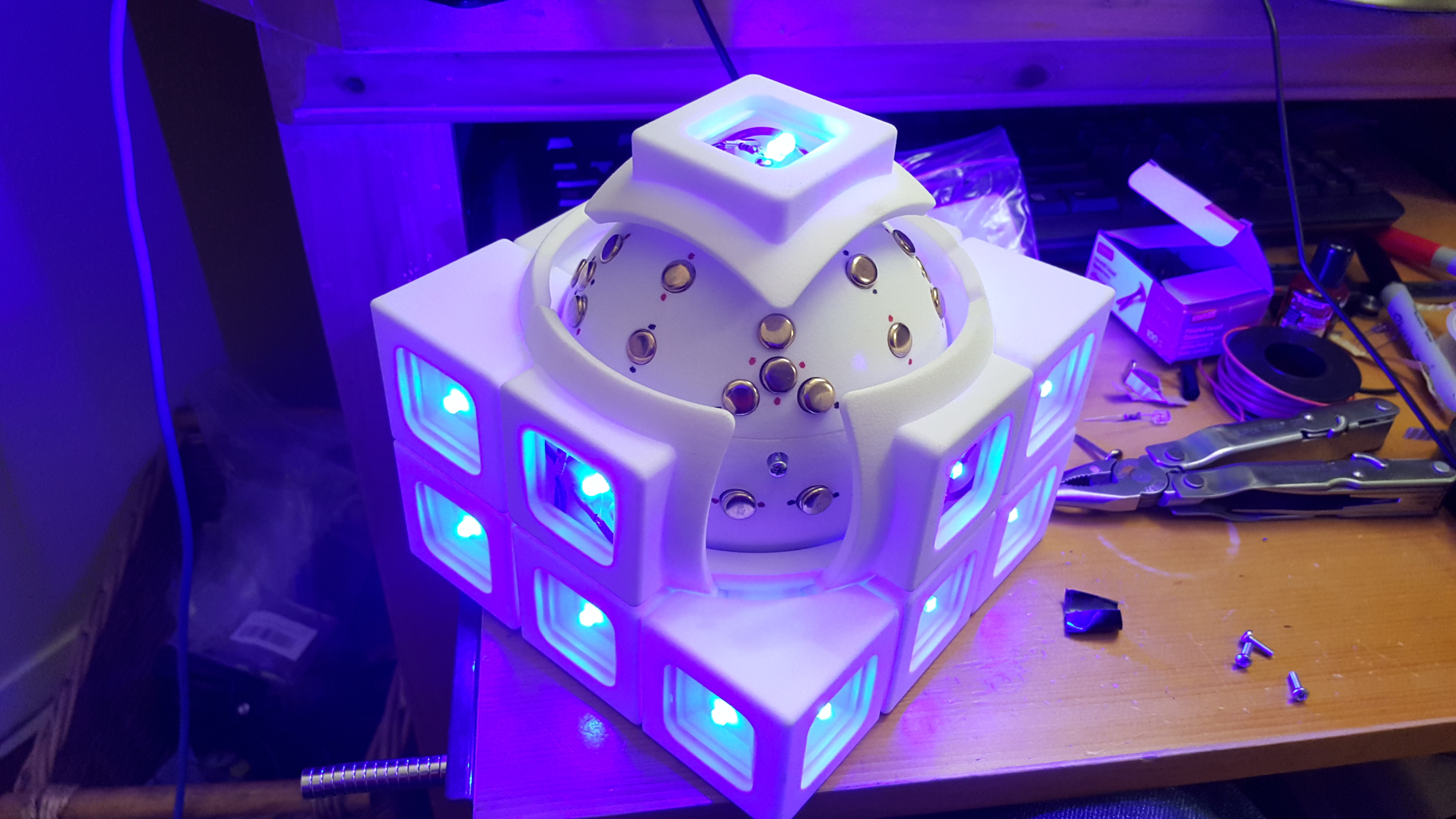
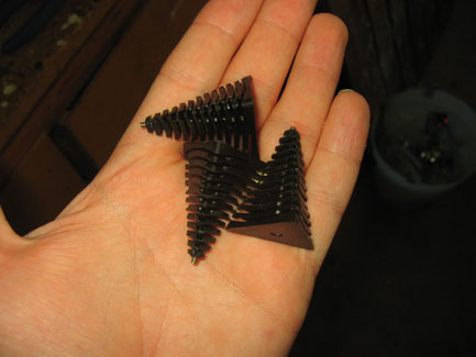
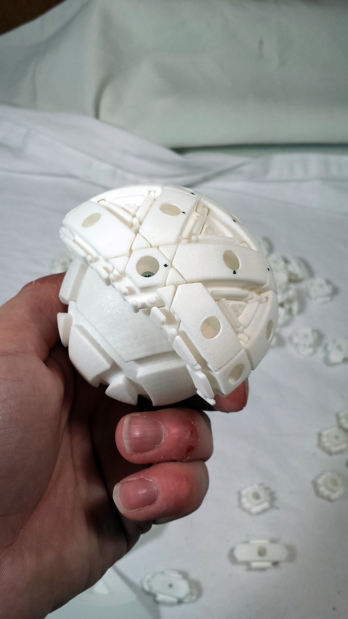
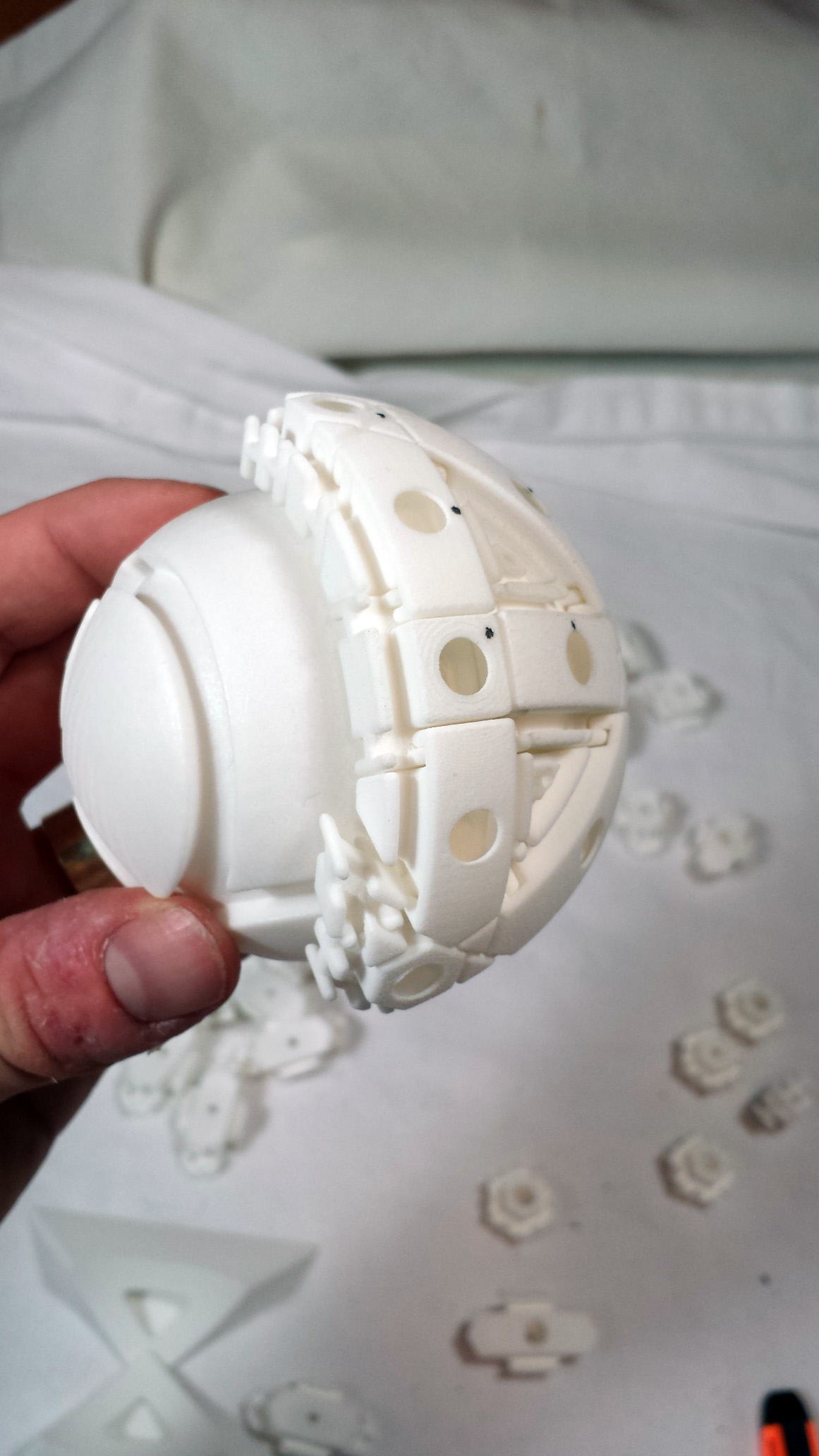
And that’s basically it! 9 years later, I have a working completed puzzle!
Thanks for reading.
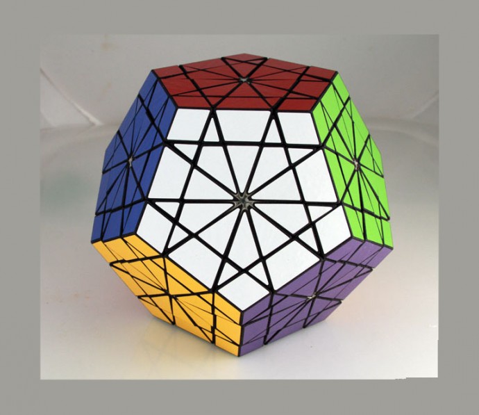
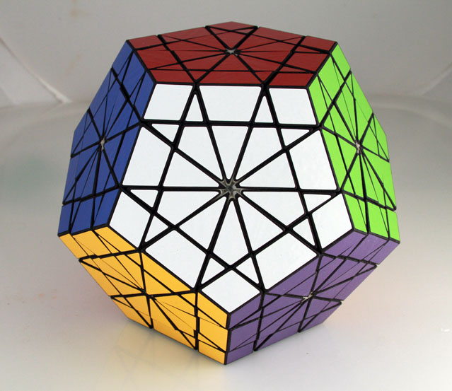
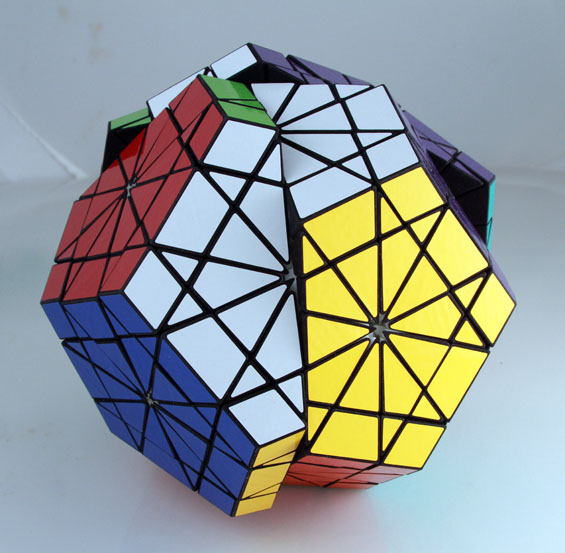
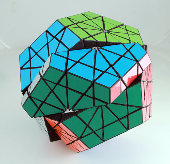
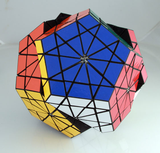
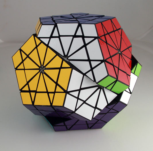
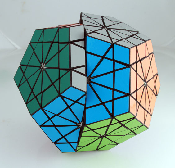
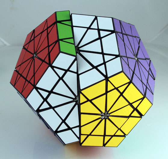
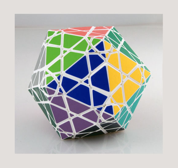
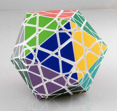
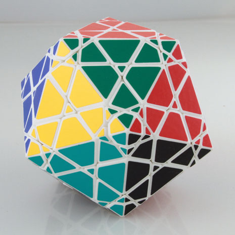


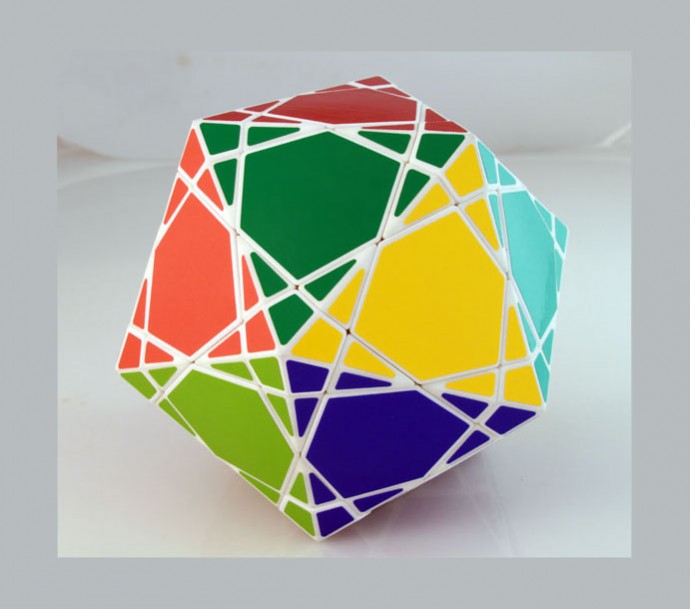
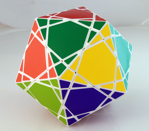
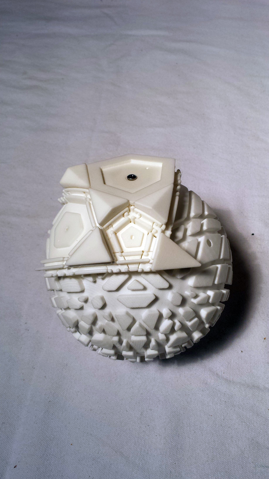
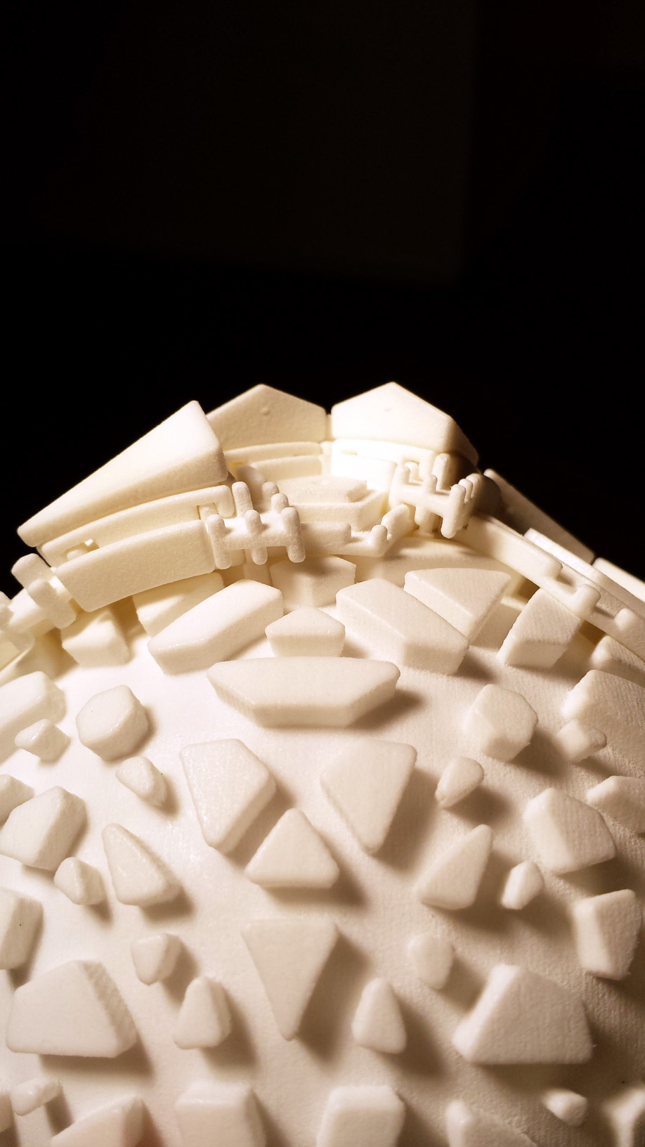
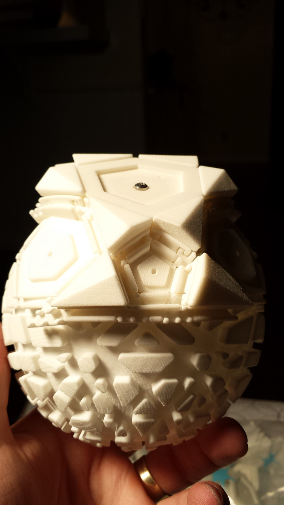

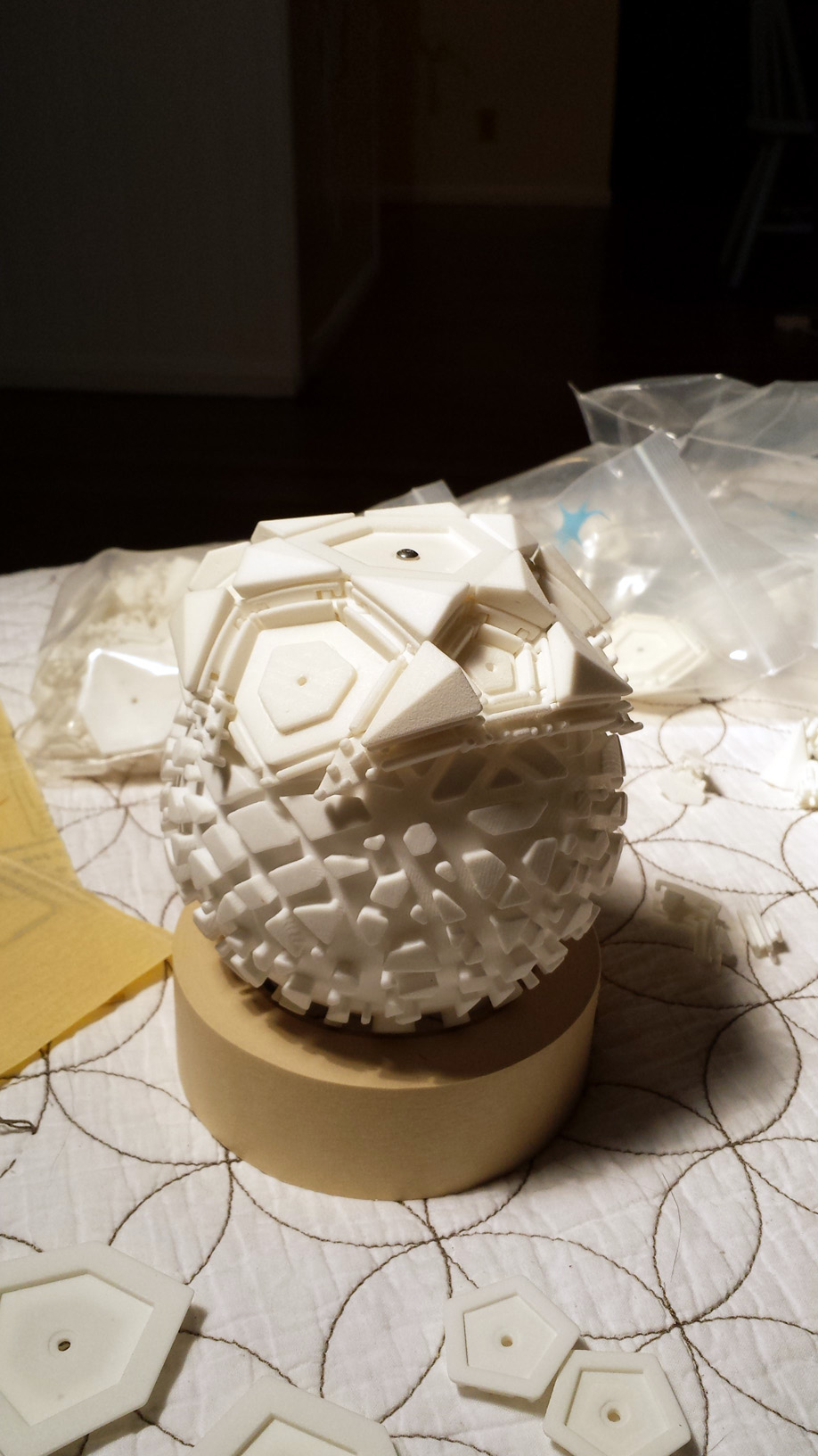

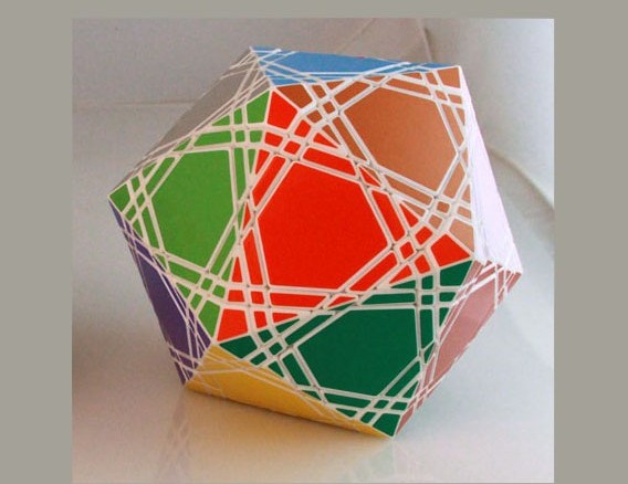
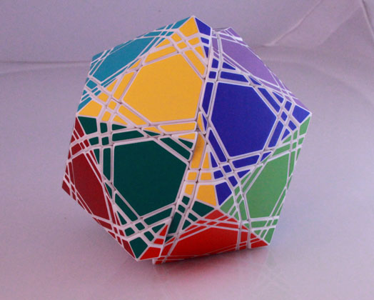
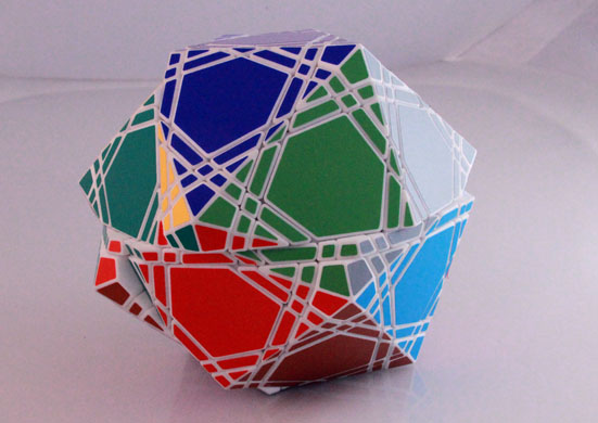
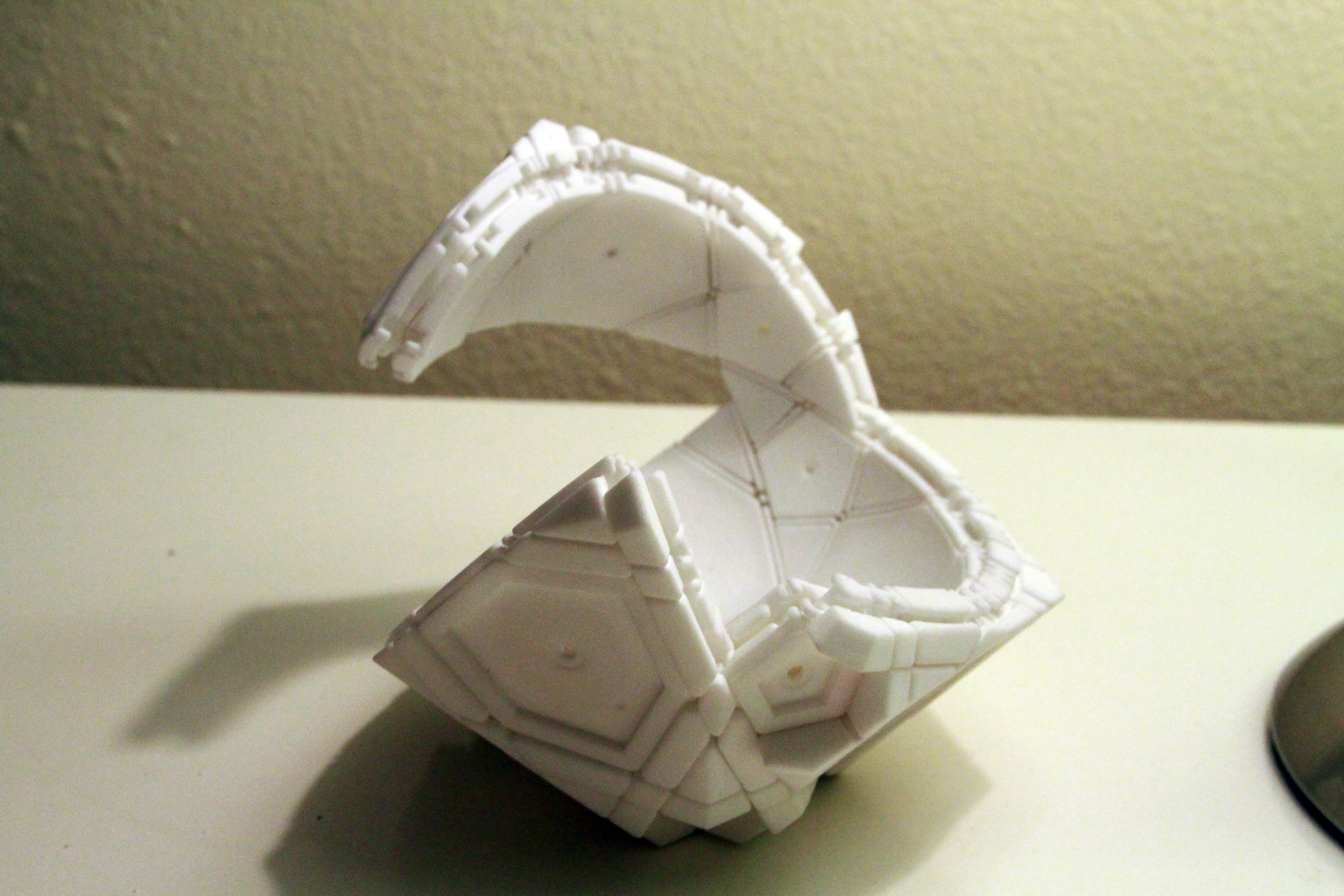
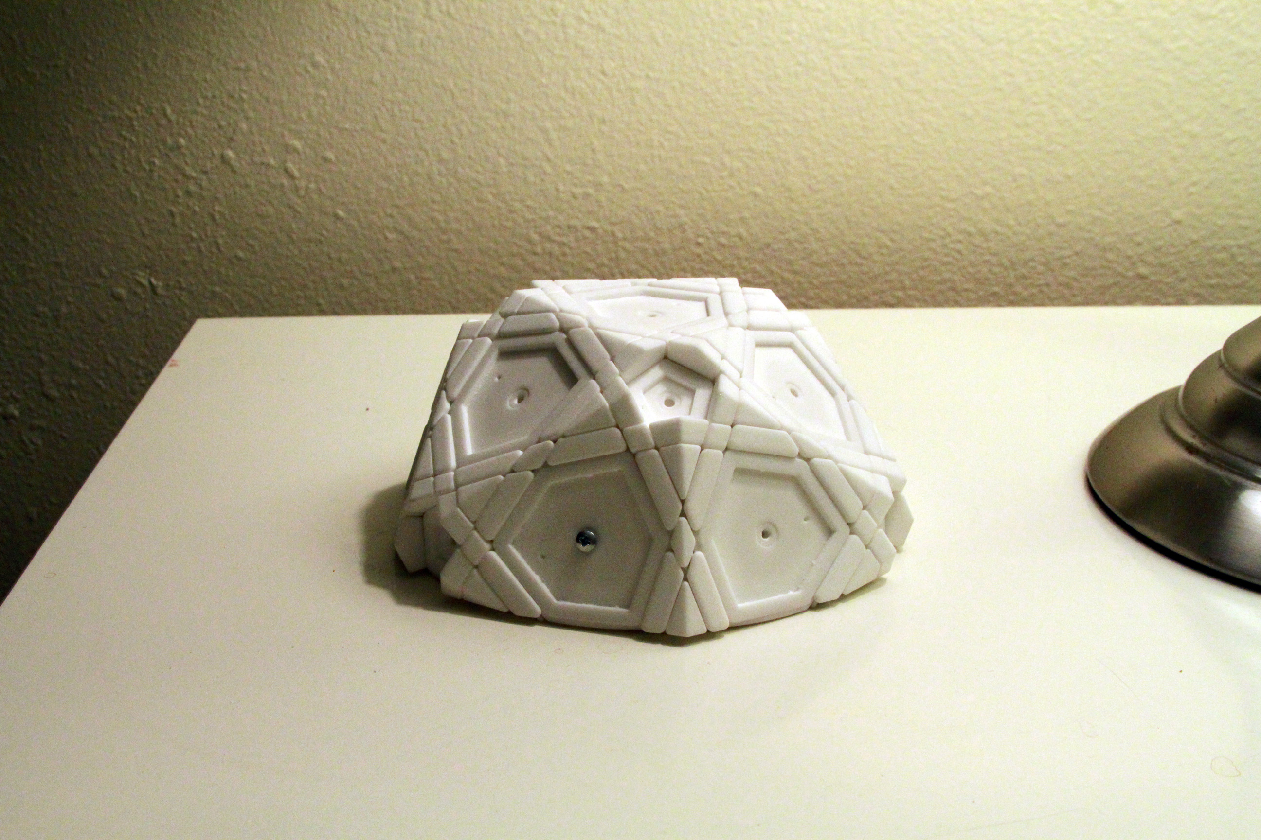
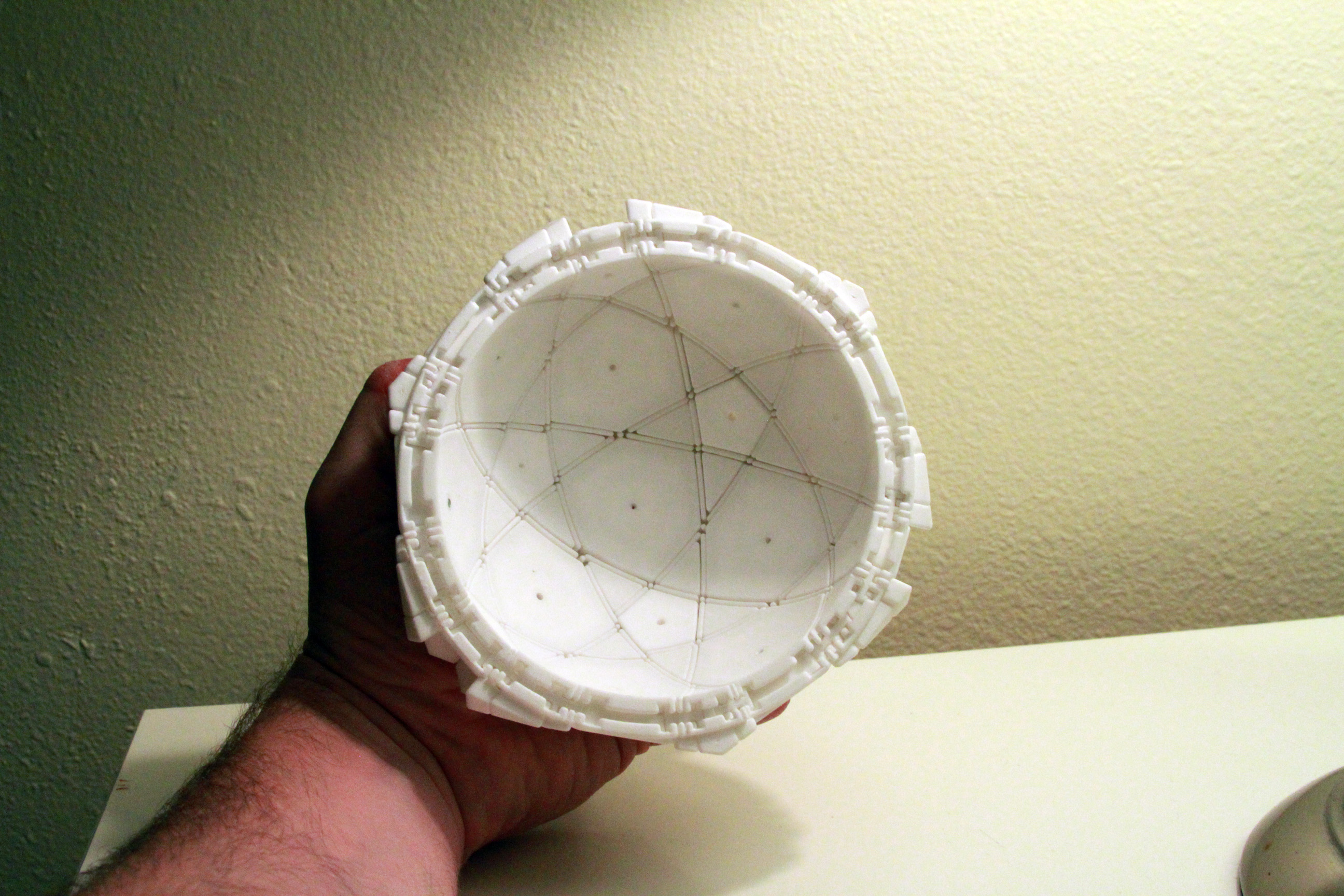
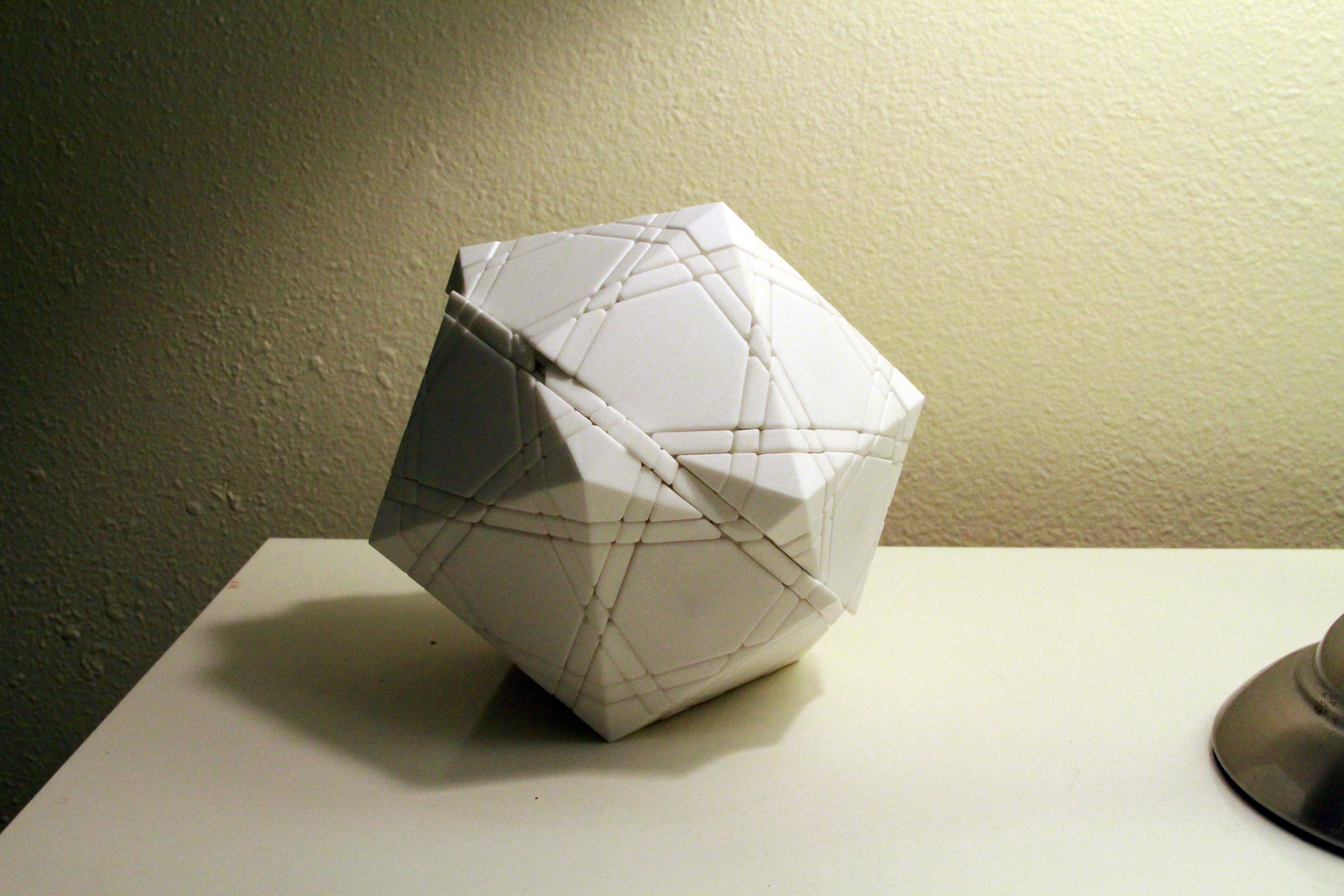
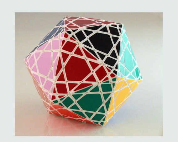
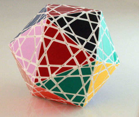
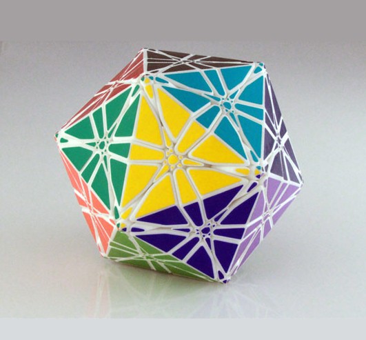

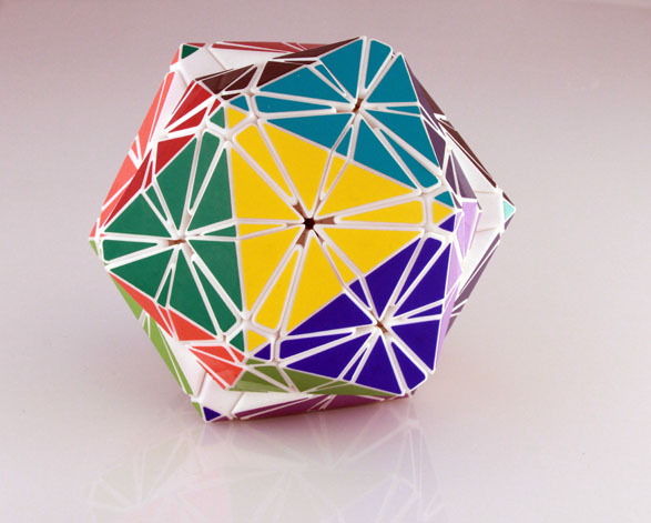
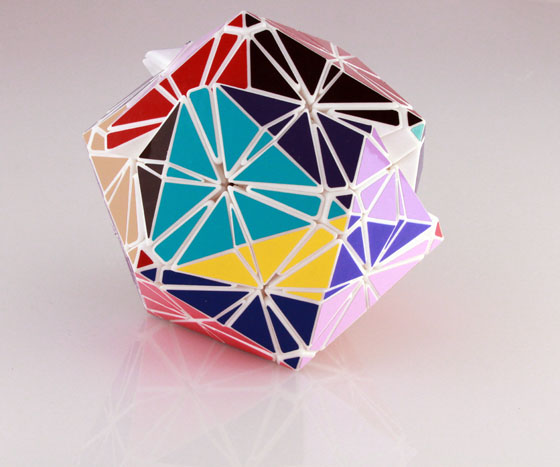

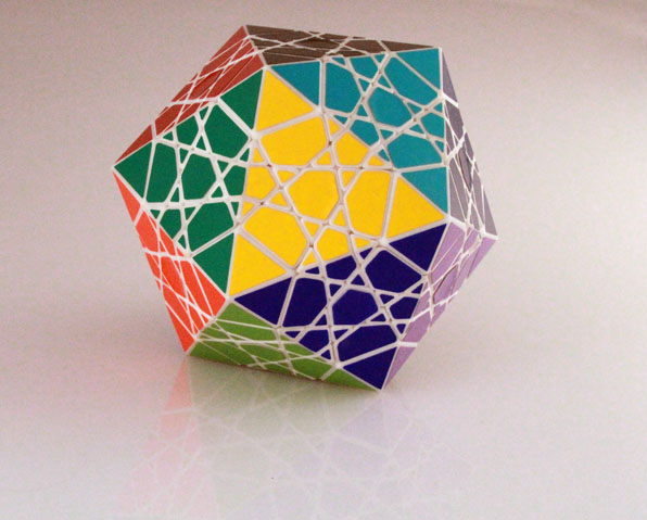
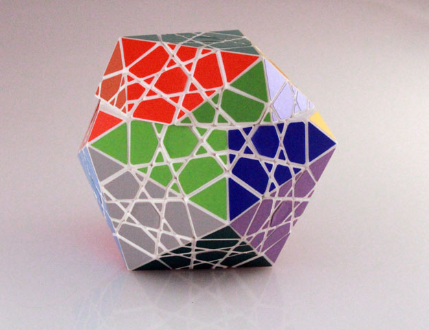
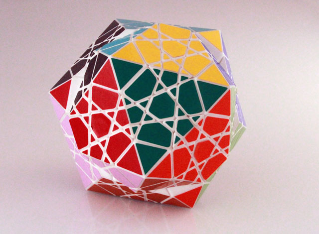

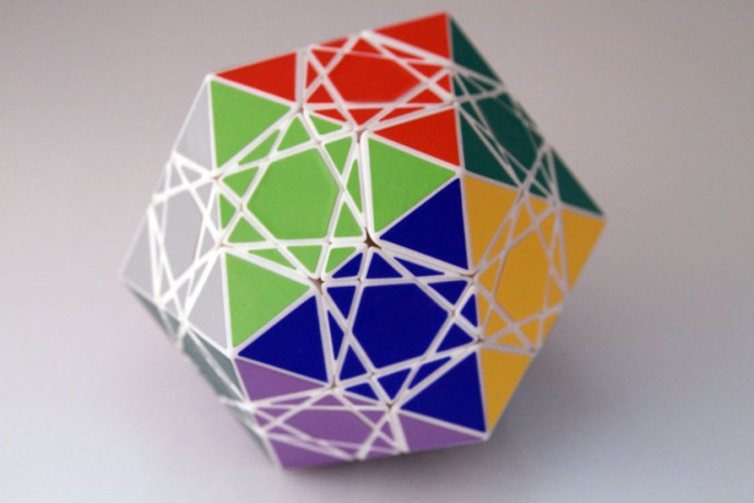


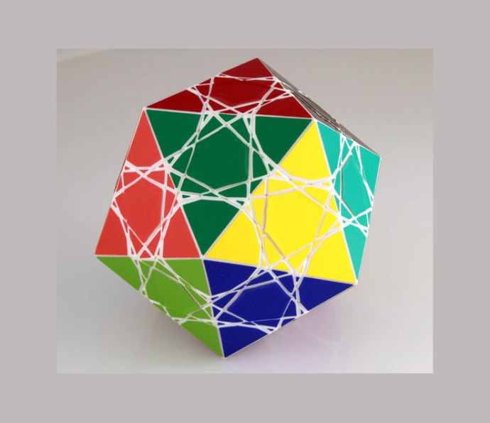

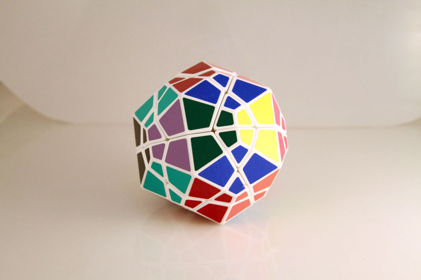
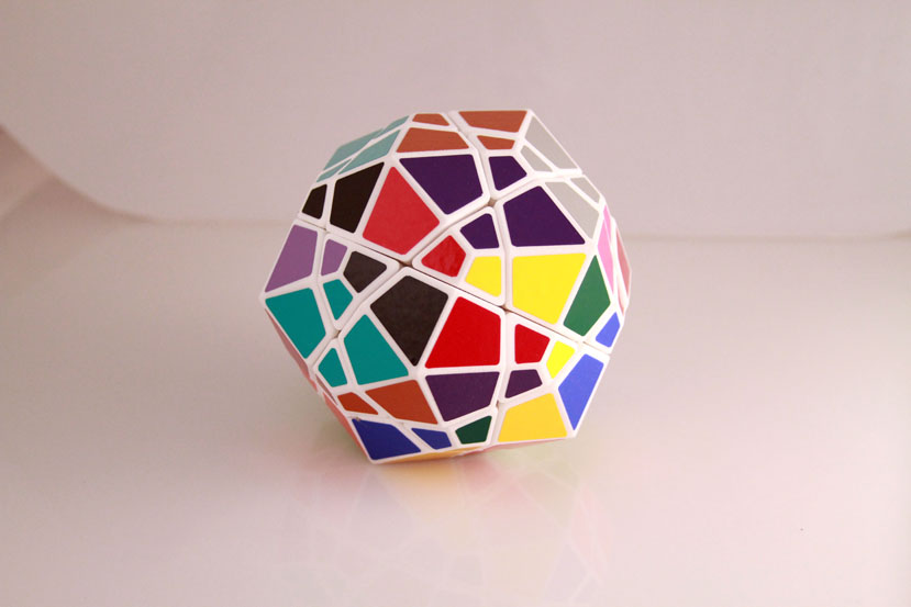


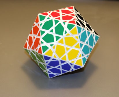


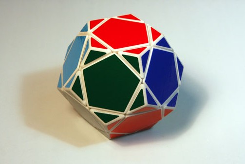
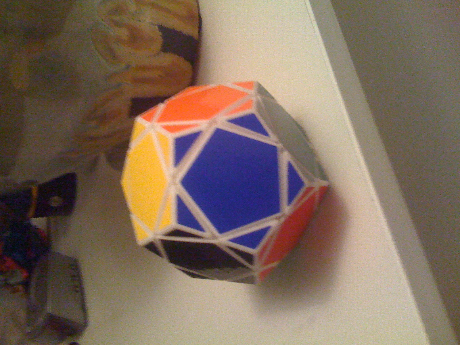
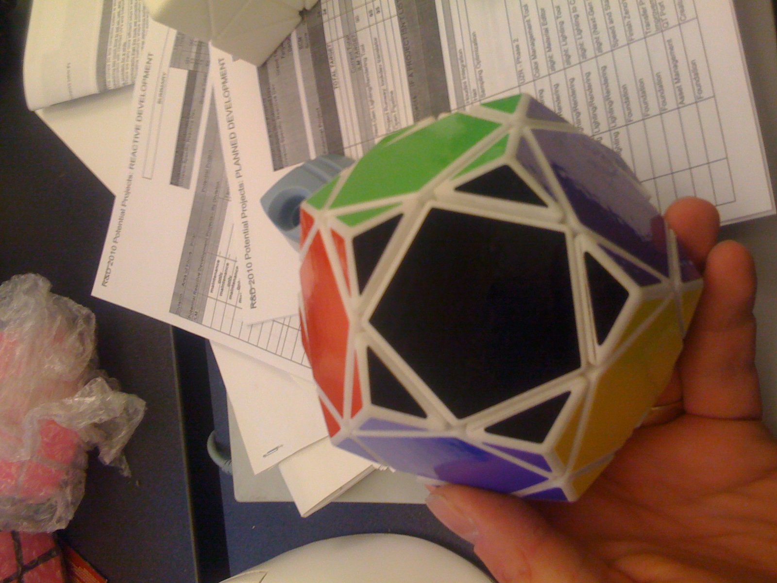

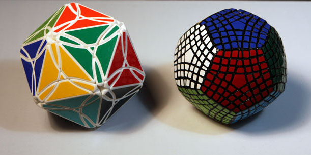
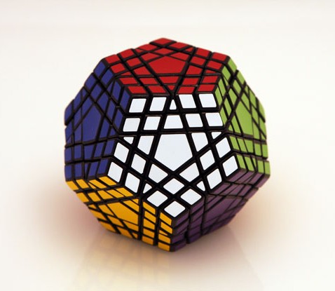
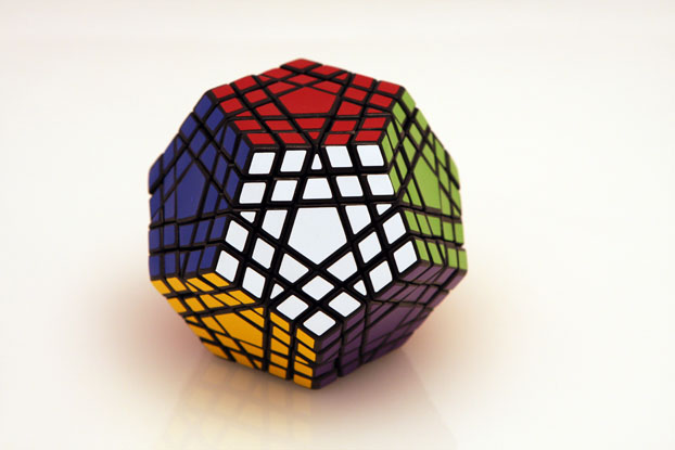
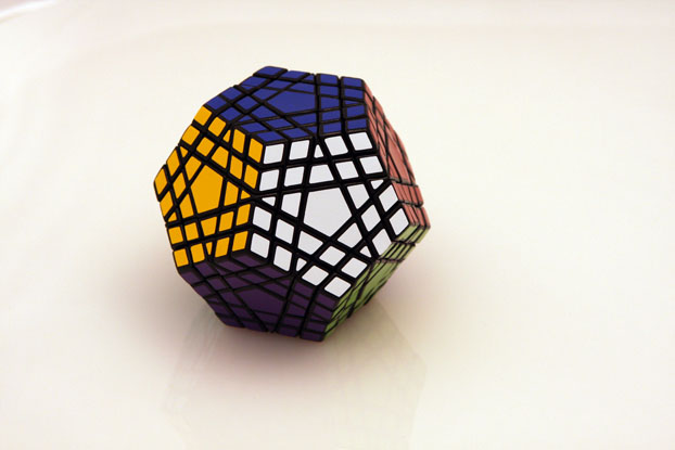
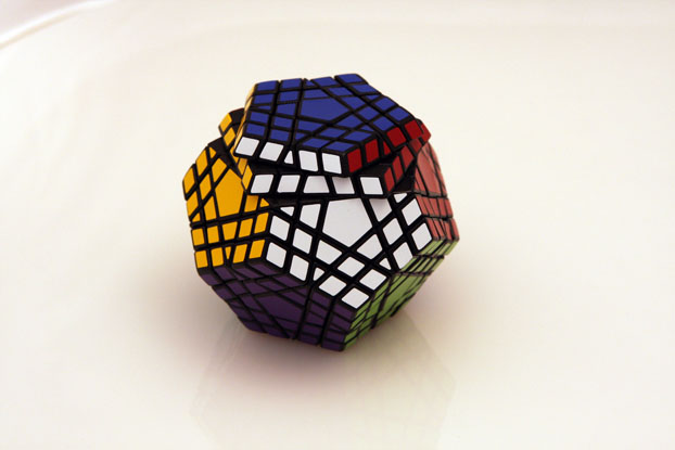
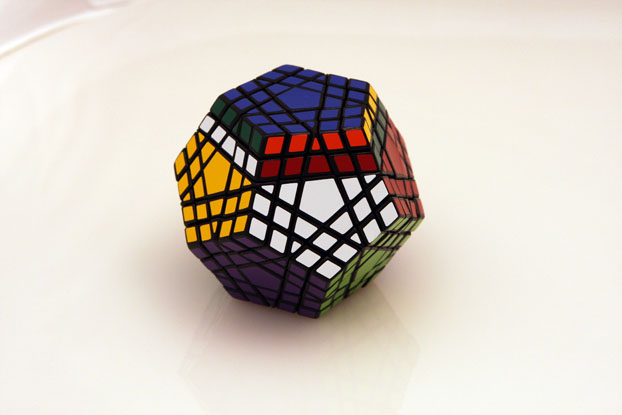

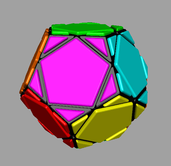
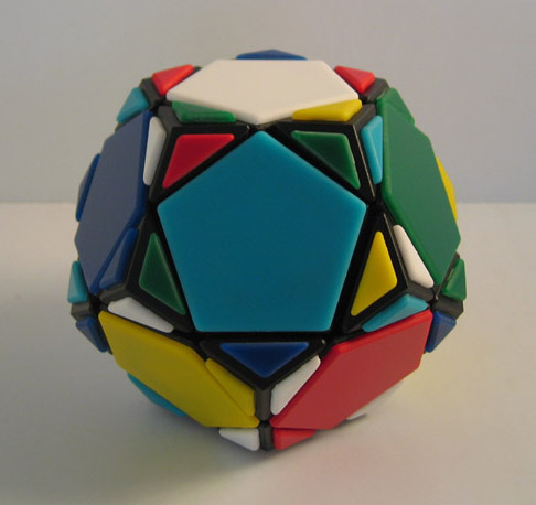
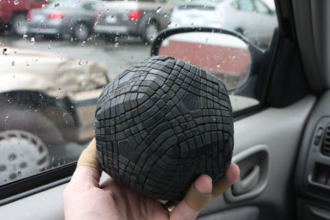
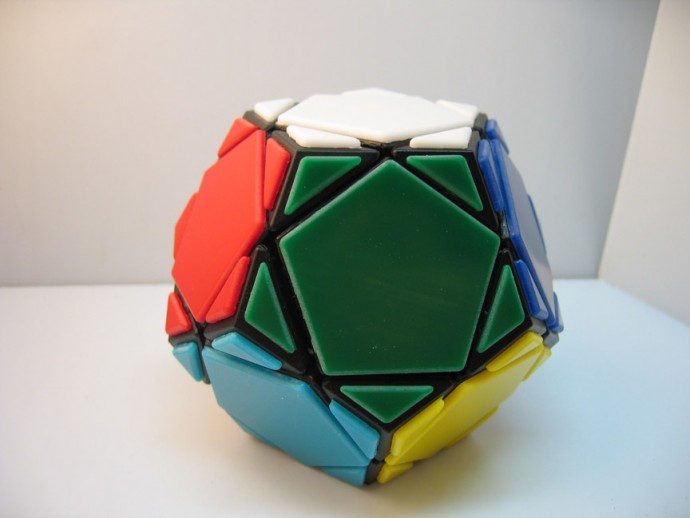
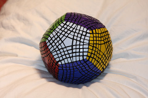 The Petaminx is a face turning dodecahedral puzzle with 4 slices per face.


 \
\